Description
Note: Many products are not yet listed. Please contact us for more product information. Our supply channels are constantly expanding, and we currently have 20 stable shared supply channels. Please confirm the model, product, price, and all other necessary information with customer service before placing an order. We offer new, refurbished, and used products, and prices are adjusted according to the year of the item you require.
Vibro-Meter VM600 IOC4T
Vibro-Meter VM600 IOC4T
3. Key Technical Specifications
| Parameter | Value |
|---|---|
| Model | IOC4T |
| Part Numbers | 200-560-000-111 (base) / 200-560-101-017 (variant) |
| Brand | Vibro-Meter |
| Product Family | VM600 (Vibration Monitoring System) |
| Number of Input Channels | 4 (individually configurable) |
| Input Signal Types | Accelerometer (IEPE), velocity (electrodynamic), proximity probe (eddy current), tachometer (speed), 4–20mA process signals |
| Input Voltage Range | ±10V AC (dynamic) / 0–24V DC (tachometer) |
| Input Impedance | 100 kΩ (voltage mode) / 50 Ω (current mode) |
| A/D Resolution | 16-bit |
| Sample Rate | Up to 50 kS/s per channel (dynamic), 1 kS/s (process) |
| Analog Outputs | 4 x 4–20mA (isolated, 500 Ω max load) |
| Relay Outputs | 4 x Form-C (SPDT), rated 250V AC / 30V DC, 2A |
| Relay Trip Delay | Configurable 0–10 seconds |
| Frequency Range | 0.5 Hz – 10 kHz (acceleration), 0.5 Hz – 2 kHz (velocity) |
| Accuracy | ±1% of full scale (at 25 °C) |
| Isolation | 500V AC (channel to channel, channel to backplane) |
| Communication | VM600 rack backplane (proprietary bus to CPU card) |
| Configuration | Via VM600 CPU card and associated software |
| Status Indicators | Green LED (OK), Red LED (fault/trip), Yellow LED (alarm) per channel |
| Operating Temperature | –20 °C to +65 °C |
| Storage Temperature | –40 °C to +85 °C |
| Humidity | 5% – 95% RH, non-condensing |
| Mounting | VM600 rack slot (plug-in module) |
| Power Consumption | 8W (typical, from rack backplane) |
| Weight | Approx. 0.4 kg (0.88 lb) |
| Certifications | CE, UL 508, API 670 (when configured in compliant rack) |
4. Product Introduction
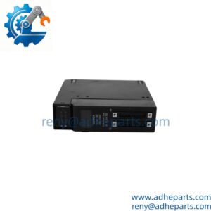
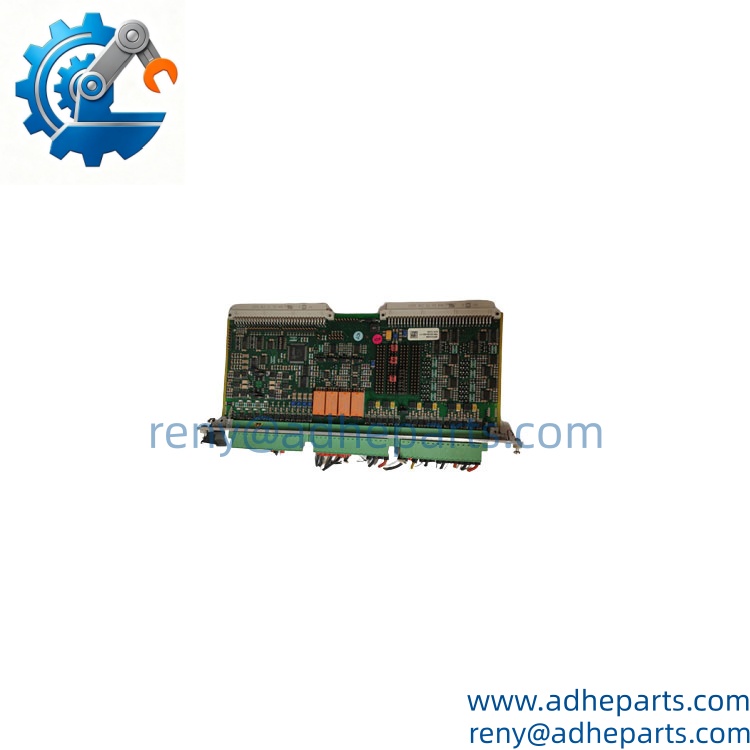
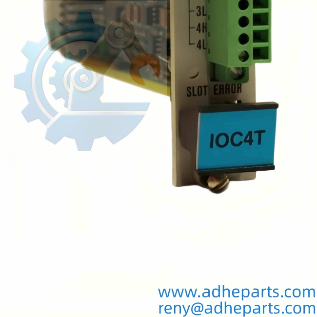
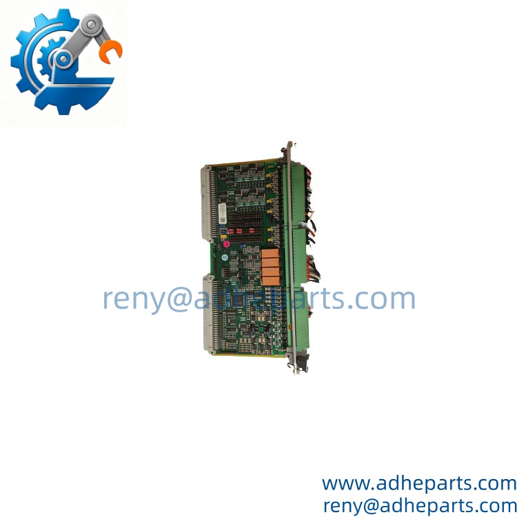
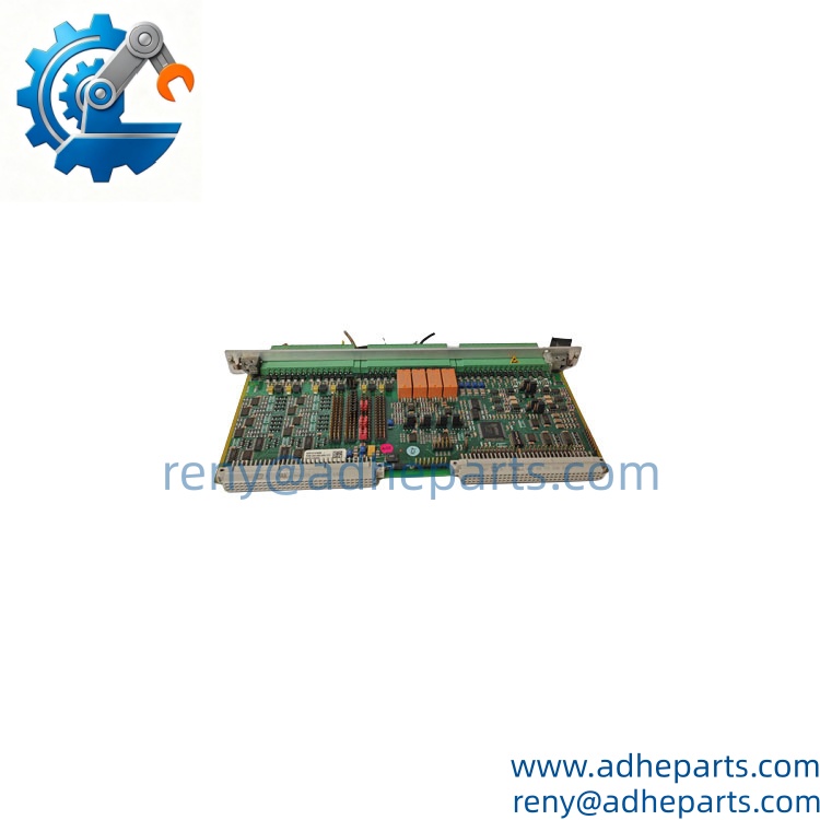
The Vibro-Meter VM600 IOC4T is a four-channel input/output card that sits inside a VM600 machinery protection rack. It is the interface between field sensors—accelerometers, proximity probes, velocity pickups, or tachometers—and the rack’s central processing unit. Each of the four channels can be configured independently for a specific sensor type, making the IOC4T a flexible building block for turbine, compressor, and pump monitoring systems. The card also provides four 4–20mA analog outputs for retransmission to a DCS or PLC, plus four relay outputs for alarm and trip functions.
What sets the IOC4T apart is the signal conditioning architecture. It uses a 16-bit ADC with a per-channel sample rate up to 50 kS/s, which captures high-frequency bearing defects and gear mesh frequencies that lower-resolution cards miss. The 500V channel-to-channel isolation prevents a ground fault on one sensor from corrupting adjacent channels—a critical feature when you have proximity probes mounted on a common shaft with different ground references. In my experience, this card is the workhorse for API 670 compliant protection systems on steam turbines and centrifugal compressors.
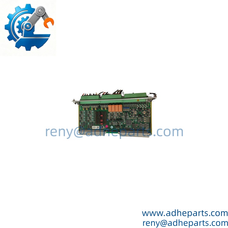
Vibro-Meter VM600 IOC4T
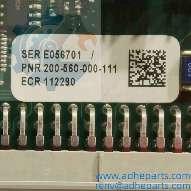
Vibro-Meter VM600 IOC4T
5. Application Scenarios & Field Experience
Part 1 – Narrative Paragraph
The biggest headache in machinery protection is false trips caused by signal noise or ground loops. I have seen a 30 MW steam turbine trip offline because a single proximity probe picked up electrical interference from a nearby variable frequency drive. The operator lost production for six hours, and the root cause was a shielding issue that a more robust input card could have filtered out. The IOC4T addresses this with its differential input stage and programmable low-pass filtering. You can set the cutoff frequency per channel to match the application—for example, 1 kHz for low-speed balance monitoring or 10 kHz for gearbox diagnostics. The relay outputs have configurable time delays, so a 20 ms noise spike does not trip the machine. That alone has saved plants from unnecessary shutdowns.
Part 2 – Numbered List (Application Scenarios)
- Power Generation – Steam Turbine Monitoring – The IOC4T connects to proximity probes measuring shaft vibration, axial displacement, and eccentricity. It sends 4–20mA signals to the DCS and trips the turbine on high vibration. The API 670 compliance ensures the protection system meets insurance and regulatory requirements.
- Oil & Gas – Centrifugal Compressor Protection – The card reads accelerometers on compressor bearings to detect early-stage bearing wear. The 50 kS/s sample rate captures high-frequency envelope data, while the relay outputs shut down the compressor before catastrophic failure.
- Petrochemical – Reciprocating Compressor Monitoring – The uses velocity transducers to monitor crosshead vibration and rod drop. The 0.5 Hz low-frequency response is essential for capturing the fundamental running speed and its harmonics.
- Hydropower – Hydro Turbine Guide Bearing Monitoring – Proximity probes measure shaft orbit and bearing clearance. The card’s channel-to-channel isolation prevents ground loop currents that are common in hydro units with large grounding grids. The 4–20mA outputs feed the plant SCADA for trend analysis.
Part 3 – Short Field Story
A natural gas processing plant had a propane compressor that would trip on “high radial vibration” every time ambient temperature rose above 95 °F. The maintenance team had replaced the probe, the extension cable, and the driver. The problem persisted. We installed a rack with an card and configured the input filter to 2 kHz instead of the previous 10 kHz setting. The high-frequency noise from a nearby pump seal was aliasing into the vibration band. After the filter change, the vibration reading dropped from 4.2 mils to 1.8 mils—well below the trip threshold. The compressor ran through the entire summer without a single false trip.
Vibro-Meter VM600 IOC4T
6. Standard Operating Procedure (SOP) for Quality Control
Every Vibro-Meter card goes through a detailed QC process before shipment:
- Visual & Origin Inspection – We verify the Vibro-Meter label, the part numbers (200-560-000-111 and 200-560-101-017), and the date code. We inspect the edge connector for bent pins or wear. Any sign of re-soldering or water damage results in rejection.
- Power-Up & Self-Test – The card is inserted into a test rack with a known-good CPU. We power up and verify the green “OK” LED illuminates. The CPU must recognize the card without a configuration error.
- Input Channel Verification – We inject calibrated signals into each of the 4 channels: a 100 mV AC sine wave at 100 Hz (simulating an accelerometer), a 1V DC signal (simulating a proximity probe), and a 24V pulse (simulating a tachometer). We verify the card’s reported values match the injected signals within ±1%.
- Output Channel Test – We command each 4–20mA output to 4 mA, 12 mA, and 20 mA. We measure the actual current into a 250 Ω load. The output must stay within ±0.1 mA of the commanded value. We also test the relay outputs by commanding them open and closed, verifying contact continuity.
- Isolation Test – We apply 500V AC between channel 1 and channel 2, and between channel 1 and the backplane connector. Leakage current must stay below 1 mA.
- Thermal Soak – The card runs at 80% of its rated input range for 2 hours in a 65 °C chamber. We monitor for communication dropouts or drift in the analog outputs.
- ESD-Safe Packaging – The card is wrapped in an anti-static bag, placed in a conductive foam insert, and packed in a rigid box with “Static Sensitive Device” labels.
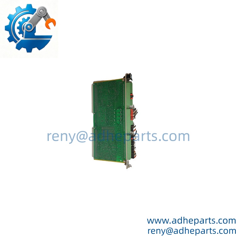
Vibro-Meter VM600 IOC4T
7. Frequently Asked Questions (FAQ)
Q1: What is the difference between part numbers 200-560-000-111 and 200-560-101-017?
A: The base part number 200-560-000-111 covers the standard card. The 200-560-101-017 suffix indicates a specific firmware or hardware revision—usually a later production run with updated component tolerances or a modified relay driver circuit. Both are functionally identical for 95% of applications. If your system requires a specific revision for compatibility with an older CPU card, check the configuration software. We can verify the exact revision before shipping.
Q2: Can the card be hot-swapped while the rack is powered?
A: No—do not hot-swap this card. The backplane does not support live insertion for I/O cards. You must power down the rack, remove the old card, insert the new one, and power back up. Hot-swapping can cause a backplane bus fault that may corrupt the CPU’s configuration memory. Always follow proper lockout/tagout procedures before working on the rack.
Q3: What sensor types does the support for each channel?
A: Each channel is software-configurable for: IEPE accelerometers (constant current 2–20 mA), electrodynamic velocity transducers, eddy current proximity probes (with -24V DC supply), tachometer signals (0–24V pulse), and 4–20mA process inputs. You cannot mix a proximity probe and an accelerometer on the same channel at the same time—configuration is per channel.
Q4: What is the warranty, and does it cover the relay outputs?
A: We offer a 12-month warranty covering all hardware failures—input channel failure, analog output drift, relay contact sticking, and backplane communication loss. The warranty does not cover damage from connecting a 24V DC sensor to a channel configured for a proximity probe (which can damage the input stage) or physical damage to the edge connector. We test every relay output before shipping and provide a test report.
Q5: Any installation pitfalls I need to watch for?
A: Two critical points. First, the requires a specific slot in the rack—check your rack’s slot assignment table. Installing it in the wrong slot will cause a backplane addressing conflict. Second, the sensor cables must be shielded and grounded at the rack end only. Grounding at both ends creates a ground loop that will inject noise into the vibration signal. We recommend using the Vibro-Meter approved cable types (e.g., 200-560-000-XXX series) for best performance. Also, verify the card’s firmware revision matches your CPU’s firmware. Mismatched revisions can cause the card to fail initialization.
Pre:Vibro-Meter VM600 CPUM 200-595-067-114 | 20kHz High-Speed Vibration Monitoring Unit
Next: Vibro-Meter IOCN 200-566-000-112 | VM600 Interface