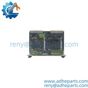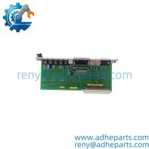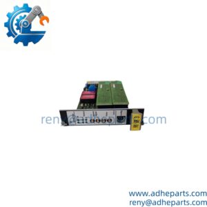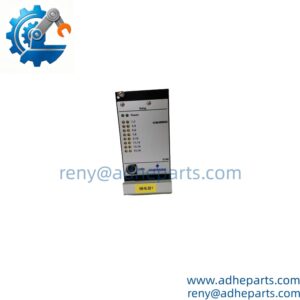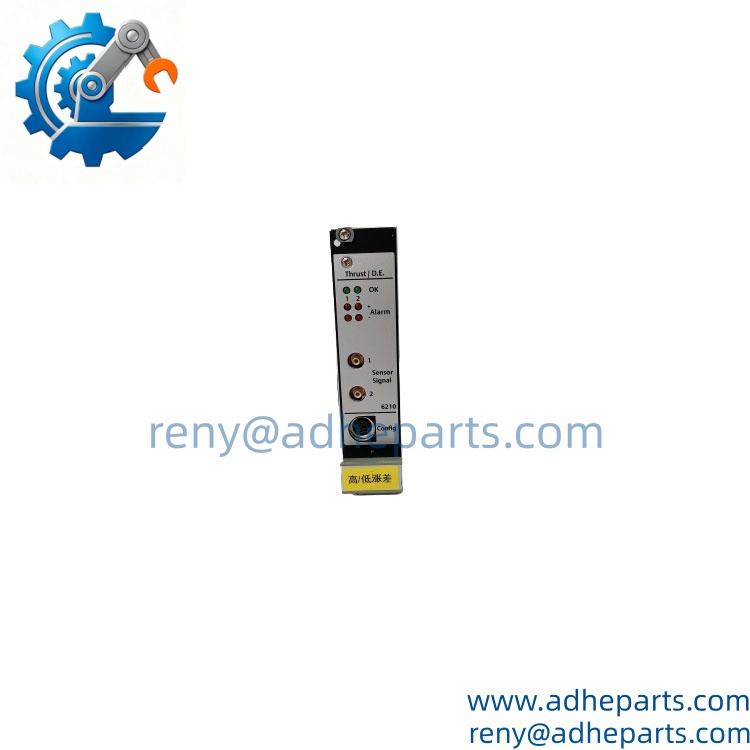
Description
To learn more about this product click on the file below or download the file:
Key Technical Specifications
| Parameter | Value |
|---|---|
| Manufacturer | Emerson / EPRO |
| Model | A6210 |
| Common Part Number | 9199-00003 |
| Product Type | Machinery Protection Monitor |
| System | CSI 6500 / AMS 6500 |
| Number of Channels | 2 independent channels |
| Measurement Modes | Thrust Position, Differential Expansion, Rod Position |
| Input Type | Eddy-current displacement transducer |
| Input Voltage Range | 0 to -22 VDC |
| Maximum Sensor Input | -26.7 VDC |
| Current Outputs | 0/4–20 mA per channel |
| Buffered Outputs | 0–10 VDC per channel |
| Output Load | <500 Ω for current output; >10 kΩ for voltage output |
| Accuracy | ±1% of full scale |
| Settling Time | Configurable, 0–10 seconds |
| Power Consumption | Max. 6 W |
| Supply | 24 VDC, approx. 250 mA |
| Rack Format | 3U Eurocard |
| Rack Space | 1 slot |
| Operating Temperature | 0°C to 65°C |
| Storage Temperature | -30°C to 85°C |
| Net Weight | Approx. 320 g |
The A6210 supports multiple measurement modes, including axial shaft movement, axial shaft position, cone/ramp/collar differential expansion, radial shaft position and bend, tandem configurations, and average rod position.
Its outputs include proportional 0/4–20 mA signals and buffered 0–10 VDC outputs. The module also provides front-panel status and buffered sensor outputs, making it suitable for both machinery protection and monitoring applications.
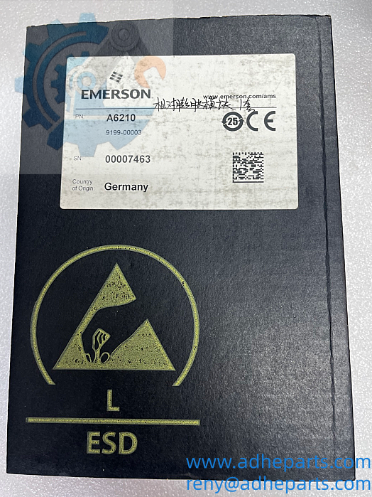
Product Introduction (Anti-Template)
When axial movement of a turbine shaft, compressor rod, or thrust-bearing assembly becomes abnormal, the A6210 provides the measurement and protection layer needed to detect that movement before mechanical damage escalates. The Emerson A6210 is a dual-channel monitor designed for thrust position, differential expansion, and rod-position measurement using compatible eddy-current displacement sensors.
The important point is that this is not simply a general-purpose vibration card. Its measurement modes and sensor interface are configured around displacement and axial-position applications. Honestly, checking the probe type and measurement range before replacing the card can save hours of troubleshooting after installation.
A typical turbomachinery protection signal flow may include:
Eddy‑current proximity probe → EMERSON‑A6210 → Rack backplane → Relay trip outputs / 4‑20 mA analog → DCS and machine safety interlock circuit
Therefore, if the customer’s existing rotating‑machinery protection system relies on this card for axial displacement safety supervision, rack chassis compatibility, sensor matching and stored configuration parameters must be confirmed before purchasing the replacement module.
QC, Procurement & Logistics SOP
- Inbound Verification
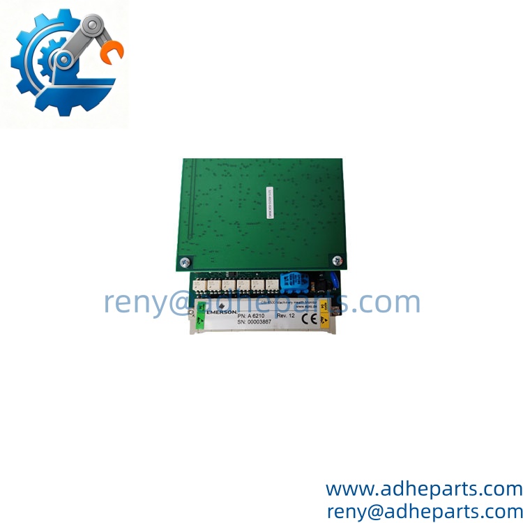
Verify the complete module identification, including A6210, part number, revision, serial number, front-panel markings, connector condition, and PCB condition. Where the customer’s original module is marked 9199-00003, record that number with the order. - Live Rig Testing
On a compatible AMS 6500 / CSI 6500 test rack, verify power-up, channel initialization, sensor input response, alarm functions, current outputs, buffered voltage outputs, and communication/status functions. For a used module, functional testing should include both channels rather than relying only on a successful power-on test. - QA & Anti-Static Packaging
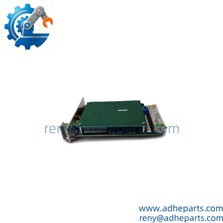
Handle the module under ESD-controlled conditions. Protect the rear connector and front-panel interface from mechanical impact. Anti-static packaging and internal cushioning should be used so the Eurocard cannot shift inside the export carton. - Global Logistics & Export Compliance
Export documents should identify the product as an Emerson Dual-Channel Thrust Position / Differential Expansion / Rod Position Monitor. HS classification should be reviewed against the actual machinery-monitoring function and destination customs requirements. Secure packaging is required for both air and sea freight to prevent connector and PCB damage.
Technical Pitfalls & Integration Warnings
- Wrong Sensor Type
The is designed for compatible displacement-transducer signals. A technician may install a mechanically similar sensor but obtain incorrect readings because the electrical characteristics do not match. Verify the existing probe and driver before commissioning. - Measurement Mode Mismatch
can operate in different modes, including thrust position, differential expansion, and rod position. Replacing the hardware without checking the configured measurement mode can produce apparently abnormal readings even when the module itself is healthy. - Output Loading Error
The current outputs have a specified permissible load of less than 500 Ω, while the 0–10 V outputs require a load greater than 10 kΩ. Connecting the wrong receiving circuit can distort the measurement signal. - ESD During Installation
The is a precision electronic monitoring card. Keep it inside anti-static packaging until installation, use proper grounding, and avoid touching connector contacts or exposed circuitry during unboxing.
Frequently Asked Questions (FAQ)
Q1: “What does the Emerson monitor?”
It monitors thrust position, differential expansion, and rod position. Depending on the configured mode, it can also measure axial shaft movement, radial shaft position/bend, tandem arrangements, and related displacement measurements.
Q2: How many channels does the have?
It provides two independent transducer input channels. Each channel can provide proportional monitoring outputs, depending on the selected configuration.
Q3: “What kind of output does it provide?”
The module provides:
- 0/4–20 mA proportional output for each channel
- 0–10 VDC buffered output
- Buffered raw sensor signals
- Front-panel alarm/status indications
The current outputs support loads below 500 Ω, while the voltage outputs are specified for loads above 10 kΩ.
Q4: Can the be hot-swapped?
Available technical documentation identifies the as a hot-configurable/hot-swappable module. Even so, the actual replacement procedure should follow the site’s approved maintenance procedure and the rack configuration. Do not remove a module from a live protection system without confirming that the system architecture permits it.
Q5: “What is the power requirement?”
The module consumes a maximum of approximately 6 W and draws about 250 mA at 24 VDC from the rack backplane.
Q6: Is a vibration monitor?
Not primarily. The is a thrust position, differential expansion, and rod-position monitor. Other modules in the same machinery protection system are dedicated to measurements such as shaft relative vibration, eccentricity, speed, and phase.
Q7: “What should I send before ordering a replacement?”
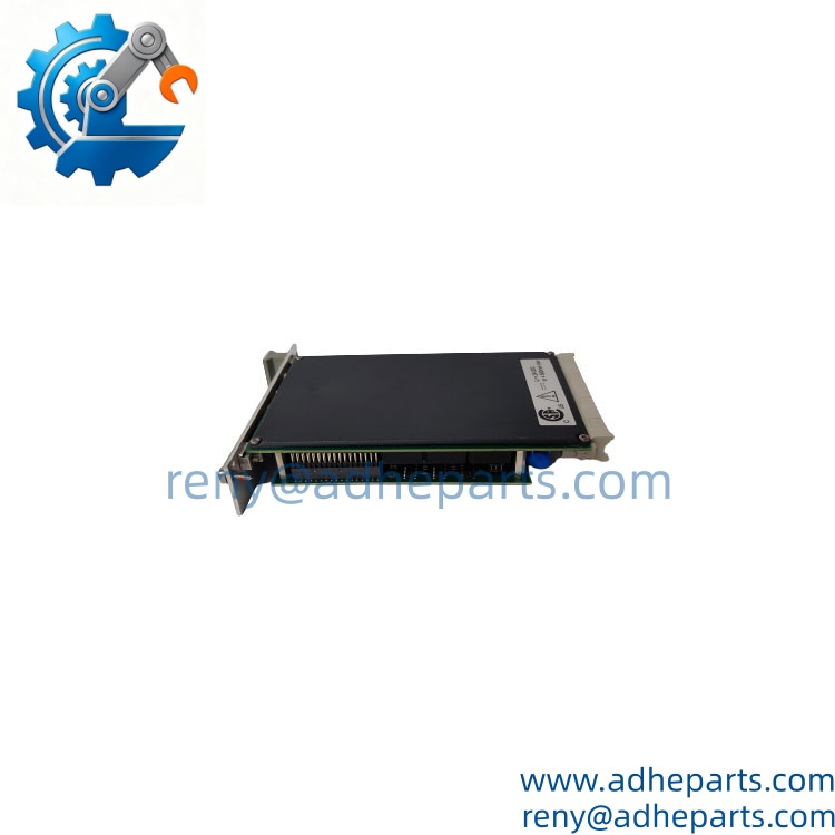
Please provide:
- nameplate photo
- Complete part number
- Hardware revision
- Existing rack model
- Sensor/probe model
- Current measurement mode
- Existing output configuration
- Quantity required
- Destination country
- Required delivery date
For this module, the sensor model and application are especially important. Two installations can use the same basic hardware while having different measurement ranges and configurations. Verify the existing setup before releasing the replacement order.
Customers who purchased this product also viewed these products:
Emerson A6110 | Shaft Relative Vibration Monitor
Emerson A6500-RC | 16-Relay Output Module