Description
Note: Many products are not yet listed. Please contact us for more product information. Our supply channels are constantly expanding, and we currently have 20 stable shared supply channels. Please confirm the model, product, price, and all other necessary information with customer service before placing an order. We offer new, refurbished, and used products, and prices are adjusted according to the year of the item you require.
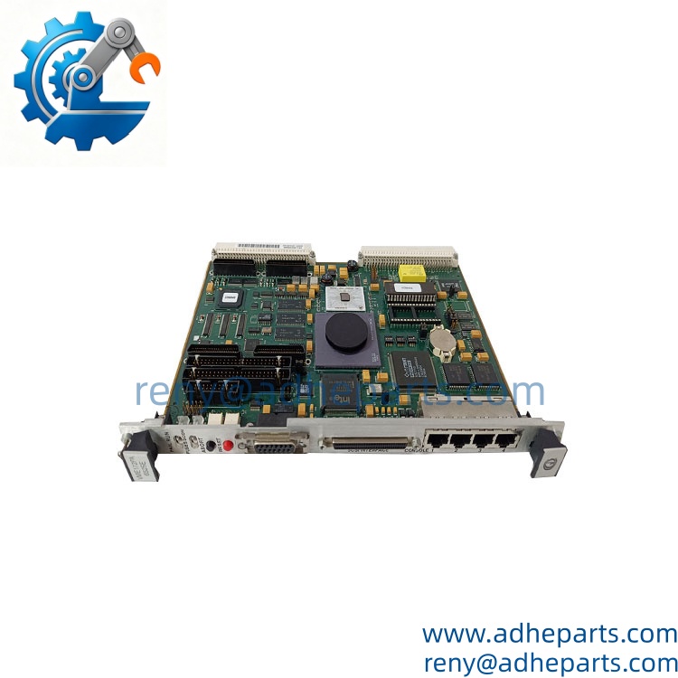
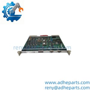
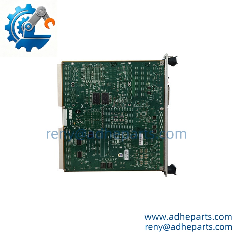
Motorola VME172PA-652SE
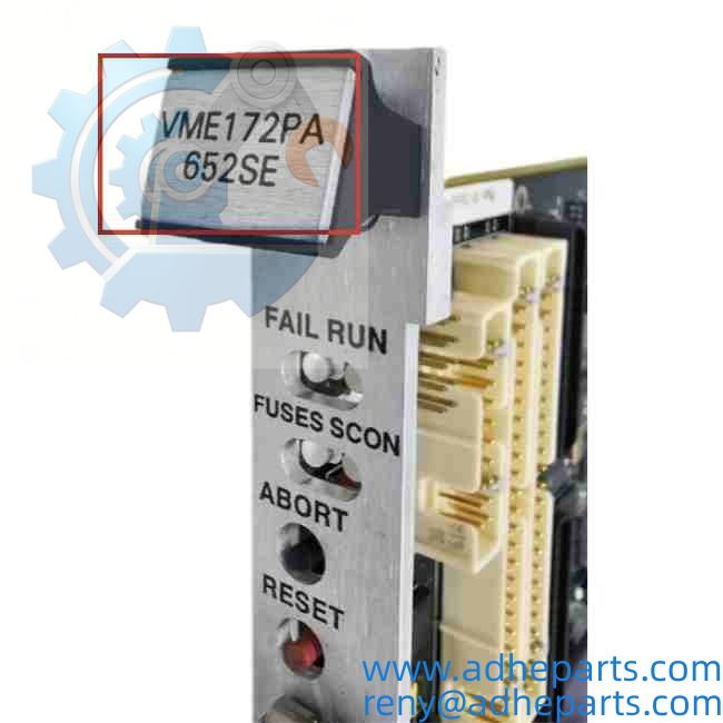
Motorola VME172PA-652SE
3. Key Technical Specifications
| Parameter | Value |
|---|---|
| Model | VME172PA-652SE (MVME172PA-652SE) |
| Brand | Motorola Computer Group |
| Product Family | MVME172 series |
| Processor | Motorola MC68060, 50 MHz |
| Cache | 8 KB instruction + 8 KB data (on-chip) |
| DRAM | 32 MB (verify option code against board label) |
| SRAM | 512 KB, battery-backed |
| Flash / Boot Memory | 2 MB (boot firmware + user image) |
| VMEbus Interface | VME64, A16/A24/A32, D8/D16/D32, master and slave |
| VMEbus Compliance | IEEE 1014-1987, ANSI/VITA 1-1994 |
| Ethernet | 10BaseT (RJ45) + AUI, onboard controller |
| SCSI | SCSI-2, 8-bit, single-ended, 10 MB/s |
| Serial Ports | 2 x EIA-232-D (DB9 front panel) |
| Parallel Port | Centronics, 8-bit |
| Timers / Counters | 4 x 16-bit programmable |
| Real-Time Clock | Battery-backed TOD clock with NVRAM |
| Debug Interface | Onboard firmware monitor (172Bug) via serial port |
| Front Panel | SCSI, Ethernet, 2 serial, reset/abort switches, status LEDs |
| Form Factor | 6U double-height Eurocard, 160 mm x 233 mm |
| Power Requirements | +5V @ 4.0A typ / +12V @ 100 mA / -12V @ 100 mA |
| Operating Temperature | 0 °C to +55 °C (standard build) |
| Storage Temperature | –40 °C to +85 °C |
| Humidity | 5% – 95% RH, non-condensing |
| Weight | Approx. 1.0 kg (2.2 lb) |
4. Product Introduction
The Motorola VME172PA-652SE is a 6U VMEbus single-board computer built around the MC68060 microprocessor. It puts the CPU, DRAM, battery-backed SRAM, flash, VMEbus interface, Ethernet, SCSI, and serial I/O on one double-height Eurocard, so a single card slot delivers a complete control node.
The engineering value is bus throughput. The board operates as both VMEbus master and slave across A32/D32 transfers, which lets it pull data from legacy I/O cards without an external bridge board. Battery-backed SRAM and 2 MB of flash hold the boot image and calibration tables through power loss.
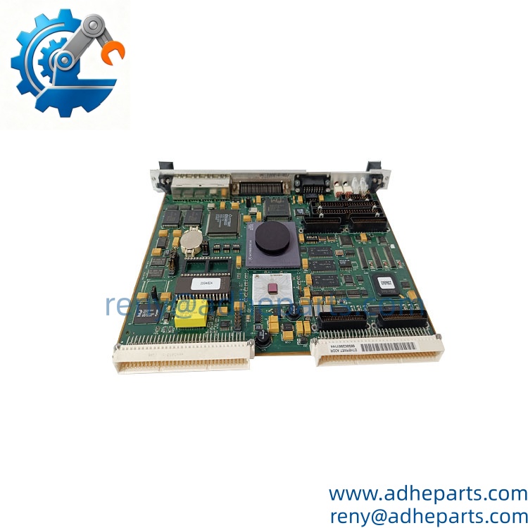
Motorola VME172PA-652SE
5. Application Scenarios & Field Experience
Part 1 – Narrative Paragraph
The problem with legacy VME racks is not that they fail—it is that they fail one card at a time, and every card removed is a chance to discover that the backplane has been running at spec limit for a decade. A 6U chassis pulling 4A on the +5V rail per CPU card has very little headroom left once you add I/O. The VME172PA-652SE solves the replacement problem directly: it drops into the same slot, speaks the same VME64 protocol, and boots from the same flash image, so the OEM application software does not need to be rebuilt. In my experience, that last point is what decides whether a line comes back up in four hours or four weeks.
Part 2 – Numbered List (Application Scenarios)
- Steel Processing – Mill Stand Data Concentrator – The board polls legacy VMEbus analog input cards at 1 ms intervals, runs the gauge control algorithm, and pushes results over Ethernet to the level 2 system. The A32/D32 master capability keeps the polling loop under budget.
- Power Generation – Turbine Retrofit Control Node – The 68060 executes the sequencer and protection logic while reading speed and vibration cards in the same rack. Battery-backed SRAM preserves the last-known state through a station battery transfer.
- Semiconductor – Wafer Handler Motion Controller – The board handles trajectory interpolation and drives a SCSI servo amplifier interface. The 50 MHz clock and 16 KB of on-chip cache keep interpolation jitter below the handler’s tolerance.
- Telecom – Legacy Signaling Node – Used in central office racks running SS7 signaling tasks. Two EIA-232 ports connect to modem banks, and the SCSI bus connects to a RAID enclosure for call detail record storage.
Part 3 – Short Field Story
A Midwest steel mill had a 1994-vintage VME rack running a bar gauge on its finishing stand. The CPU card failed a POST check and refused to boot—no fan, no output, dead. The mill had no spare and the OEM quoted 14 weeks. We shipped a VME172PA-652SE the same day. The mill’s technician moved the SCSI drive and the flash card across, powered the rack up, and the firmware monitor came back with a clean memory map. The stand was rolling again the next morning.
6. Standard Operating Procedure (SOP) for Quality Control
Every VME172PA-652SE board is processed through this QC sequence before it is cleared for shipment:
- Visual & Origin Inspection – We verify the Motorola silkscreen, the option code on the board label, and the date code. We inspect the 96-pin DIN P1/P2 connectors for bent pins, cracked solder joints, and corrosion. Any board showing rework outside the factory pattern is rejected.
- Power Rail Verification – We apply +5V, +12V, and -12V from a bench supply and measure current draw at idle. A standard board pulls roughly 4.0A on the +5V rail. A board drawing more than 15% above baseline is pulled for inspection.
- POST and Firmware Monitor Test – We connect a terminal to the front-panel serial port and watch the boot sequence. We verify the firmware monitor banner, run a memory map dump, and check the DRAM and SRAM address ranges against the option code.
- Memory Integrity Test – We write a walking-ones pattern across all DRAM, read it back, and compare. We do the same for the 512 KB SRAM with the battery disconnected and then reconnected, to confirm the cell holds state.
- VMEbus Master/Slave Test – The board is installed in a powered 6U chassis alongside a known-good I/O card. We run master reads and writes across A16, A24, and A32 spaces, and verify slave access from an external VMEbus master.
- Peripheral Verification – Ethernet is tested with a loopback plug at 10BaseT. SCSI is tested with a terminated loopback cable. Both serial ports are exercised with a null-modem loopback at 9600 and 115200 baud.
- Battery Replacement – We measure the onboard lithium cell under load. Any cell reading below 3.0V is replaced with a fresh unit, and the date code is recorded on the test sheet.
- ESD-Safe Packaging – The board is wrapped in anti-static film, seated in a conductive foam insert with the edge connector protected by a rigid shroud, and packed in a double-wall carton with static warning labels.
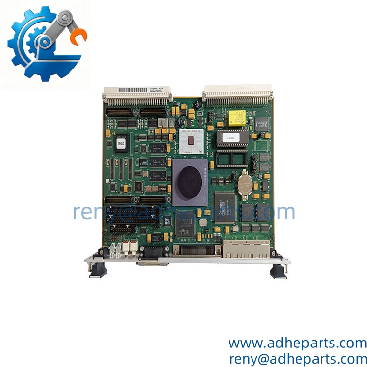
Motorola VME172PA-652SE
Motorola VME172PA-652SE
7. Frequently Asked Questions (FAQ)
Q1: Will this board drop into a slot that currently holds an MVME172PA-644SE?
A: Mechanically yes—same 6U form factor, same P1/P2 connectors, same slot keying. Electrically, check two things. First, the 644SE uses a slower processor variant, so if your application firmware was compiled with a timing-dependent loop, re-verify the scan budget. Second, confirm your chassis power supply can carry the extra +5V current. If the 644SE was already near the supply’s limit, adding a 50 MHz board can push it over.
Q2: What is the warranty, and what does it cover?
A: We offer a 12-month warranty from the ship date. It covers processor failure, memory faults, VMEbus interface faults, and onboard peripheral controller failures under normal operating conditions. It does not cover damage from reverse-polarity power application, bent connector pins from forced insertion, or ESD damage from handling without a wrist strap. The lithium backup cell is a consumable—we install a fresh one before shipping, but we do not warranty its capacity beyond 30 days.
Q3: Do you actually have these in stock, or is this a lead-time item?
A: The MVME172 series is end-of-life, so all inventory is surplus or refurbished. We hold stock of the VME172PA-652SE in small quantities and ship same-day or next-day when units are on the shelf. Quantities above five units usually require a stock check. If we do not have it, we will tell you the real number instead of quoting a fabricated lead time.
Q4: My existing board runs an older firmware monitor. Will a newer revision cause problems?
A: It can. The MVME172 firmware monitor is stored in flash or EPROM, and different revisions changed the memory map defaults and the SCSI initialization sequence. If your application makes assumptions about where the monitor places its stack or how it enumerates the SCSI bus, a newer revision can hang the boot. Before ordering, read the revision string off your existing board’s serial banner and compare it to ours. We can flash a specific revision on request if we have the image.
Q5: Any installation pitfalls I should watch for?
A: Three. First, the leftmost slot in most VME chassis is wired as slot 1 and carries the system controller function—if you are replacing the controller card, the board must go there. Second, the VMEbus requires proper termination at both ends of the backplane. If you pull a terminated card and leave the end unterminated, you will get intermittent bus errors that look like software bugs. Third, always power the chassis down before inserting or removing the board. These cards are not hot-swap capable, and live insertion can arc the P1 connector pins.
Pre: Vibro-Meter VM600 RPS6U 200-582-600-013 | 24V DC 4A Industrial Power Unit
Next: GE VMIVME-4116 8-Channel ±10V DAC Board