Description
Note: Many products are not yet listed. Please contact us for more product information. Our supply channels are constantly expanding, and we currently have 20 stable shared supply channels. Please confirm the model, product, price, and all other necessary information with customer service before placing an order. We offer new, refurbished, and used products, and prices are adjusted according to the year of the item you require.
3. Key Technical Specifications
Confirm each line against the OEM datasheet and the label on your existing module before ordering. The terminal panel part number and the load ratings must be verified for your specific configuration.
| Parameter | Value |
|---|---|
| Model | 3401 |
| Brand | Triconex |
| Product Family | Tricon v9 / v10 |
| Module Type | Digital Output Module (DOM) |
| Output Points | 32 (verify with OEM datasheet for your build) |
| Output Voltage | 24V DC nominal — verify range |
| Output Type | Sourcing or sinking — verify against your field wiring configuration |
| Architecture | Triple Modular Redundant (TMR) |
| Safety Integrity Level | SIL 3 capable when configured in a compliant Tricon system |
| Diagnostics | Output loopback and stuck-on/stuck-off detection |
| Isolation | Field side to logic side — verify isolation voltage |
| Backplane Interface | Tricon chassis backplane — verify slot assignment |
| Terminal Panel | External terminal panel required — verify the correct part number for your chassis and marshalling |
| Load Current per Point | Verify with OEM datasheet |
| Total Module Current | Verify with OEM datasheet |
| Compatible Chassis | Tricon main and expansion chassis — verify chassis model and revision |
| Hot Swap | Supported in redundant configuration — follow the OEM procedure; do not pull under load without verifying |
| Status Indicators | Module health and point status LEDs — verify arrangement |
| Operating Temperature | 0 °C to +60 °C (typical — verify) |
| Storage Temperature | –40 °C to +85 °C (typical — verify) |
| Humidity | 5% – 95% RH, non-condensing |
| Weight | Verify with OEM datasheet |
| Certifications | TÜV SIL 3, CE, UL — verify on the specific unit’s label |
4. Product Introduction
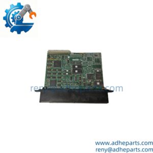
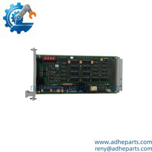
The Triconex 3401 is a digital output module for the Tricon safety system. It drives 24V DC field loads — solenoid valves, relay coils, pilot lights, and actuator commands — from a triple-modular-redundant architecture that keeps the output correct even when one of the three internal channels faults. It is the module that executes the final control action in a safety instrumented function.
The engineering value is the TMR output voting. Each output point has three independent drive circuits, and the module votes the result before it reaches the field terminal. If one channel shorts or opens, the other two carry the command and the module reports the degraded channel to the controller. That is what allows a Tricon system to reach SIL 3 without a shutdown for every single internal fault.
Two things decide whether a swap works. First, the terminal panel. The 3401 does not land field wiring directly — it mates with an external terminal panel that carries the marshalling and the field connections. If the panel is wired for a different module type or a different point count, the replacement will not work. Second, the chassis revision. Verify the chassis supports the module revision before you install it.
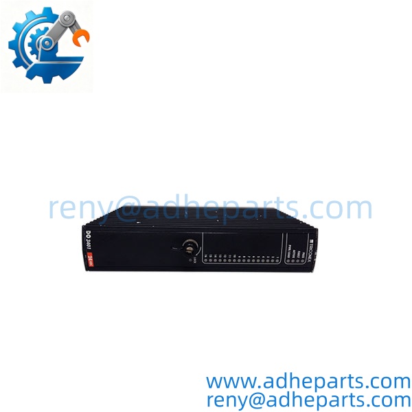
Triconex 3401
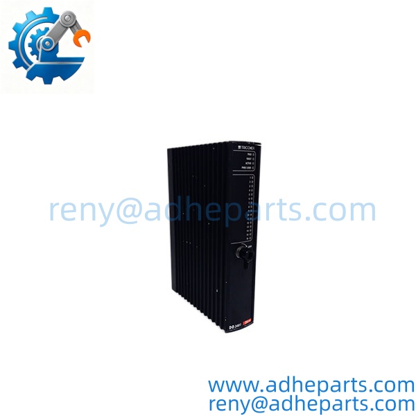
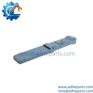
Triconex 3401
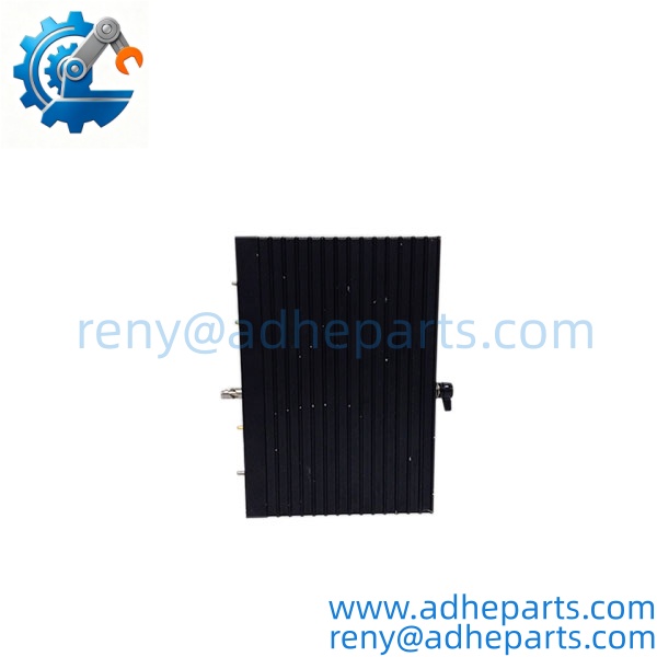
Triconex 3401
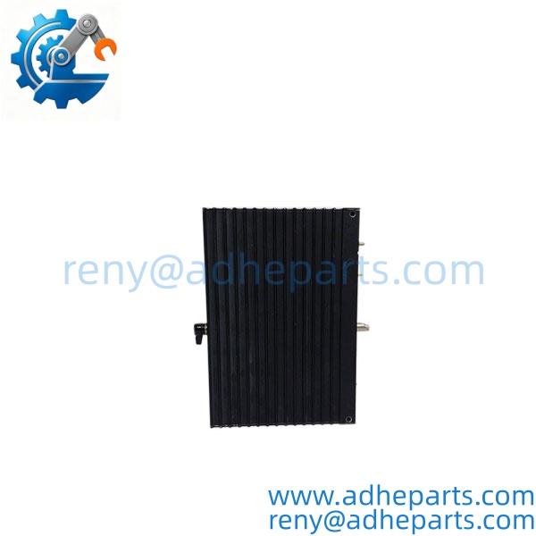
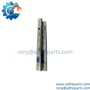
Triconex 3401
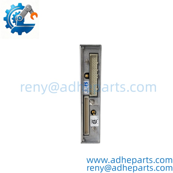
Triconex 3401
5. Application Scenarios & Field Experience
Part 1 – Narrative Paragraph
The failure that hurts most on a safety output module is not a dead channel — it is a channel that reads healthy and still fails to drive the load. The controller sees the command, the module reports no fault, and the field device does not energize. I have seen that on an ESD valve circuit where the output module was passing its loopback test but the field terminal was not getting the voltage. The root cause was a failed output driver that the diagnostic circuit could not see because the load was too light to register. On a safety system, that is the failure mode that keeps you up at night. When you replace a Tricon output module, verify the output at the field terminal — not just at the module — before you return the loop to service.
Part 2 – Numbered List (Application Scenarios)
- Oil & Gas – Emergency Shutdown Valve Control – The module drives solenoid pilot valves on ESD valves. The TMR architecture keeps the valve command correct through a single channel fault, and the diagnostics report the degraded channel to the operator.
- Chemical – Reactor Trip and Interlock Outputs – Used to command shutdown valves and isolation dampers on exothermic reactor systems. The stuck-on and stuck-off detection helps isolate a failed output before it defeats the safety function.
- Power Generation – Burner Management System Outputs – Drives fuel shutoff valve solenoids and igniter commands. The SIL 3 rating meets the burner management safety requirements.
- Pipeline – Compressor Station Shutdown Outputs – Commands the shutdown valves and the motor trip circuits at remote compressor stations. The module’s diagnostics log the fault to the safety controller for maintenance follow-up.
Part 3 – Short Field Story
A Gulf Coast refinery had an ESD valve on a hydrogen unit that failed to close during a proof test. The controller commanded the closure, the output module showed the point as energized, and the valve did not move. The maintenance team replaced the solenoid and the valve still would not close. We asked them to measure the voltage at the field terminal with the output commanded on. It read 19V DC — enough to register as “on” in the loopback circuit but not enough to pull in the solenoid. The output driver had degraded, and the diagnostic circuit could not see it because the module’s internal test load was lighter than the field load. The plant replaced the 3401 module, re-ran the proof test, and the valve closed in the required time. The module had been reporting healthy the entire time.
6. Standard Operating Procedure (SOP) for Quality Control
- Visual & Origin Inspection – We verify the Triconex marking, the 3401 model string, and the date code. We inspect the backplane connector for bent pins and the module housing for cracks or moisture ingress. A module with a damaged connector or evidence of rework is rejected.
- Revision and Firmware Documentation – We read and photograph the full model string, the firmware revision, and the module revision letter. That record ships with the module so you can compare it against the unit you are replacing.
- Chassis Fit Verification – Each module is seated in a Tricon test chassis to confirm the connector engages fully and the retention mechanism holds. A module that fits loosely will cause intermittent backplane faults in the field.
- Power-Up and Self-Test – The module is powered in a live chassis and we verify it completes its boot sequence and that the controller recognizes the module type without a fault.
- Output Channel Verification – We command each output point to the on and off state and verify the output voltage and current into a calibrated load bank. We test at the rated load and at a light load to catch the degraded-driver failure mode.
- Diagnostic Function Test – We simulate an open field loop and a stuck output and verify the module reports the fault to the controller. A module that drives the load correctly but does not report faults is not acceptable for safety service.
- Isolation Test – We apply the rated isolation voltage between the field side and the logic side. Leakage current must stay below the datasheet limit.
- ESD-Safe Packaging – The module is wrapped in anti-static film, seated in a conductive foam insert with the connectors protected by rigid shrouds, and packed in a double-wall carton with static warning labels.
7. Frequently Asked Questions (FAQ)
Q1: Does the 3401 include the terminal panel?
A: No. The 3401 is the module only. Field wiring lands on an external terminal panel that mates with the module through the chassis. The terminal panel is a separate part number, and you must verify it matches your module type, point count, and chassis. If you send us the terminal panel part number and the chassis model, we can confirm the match before you order.
Q2: Can I hot-swap the 3401 in a running Tricon system?
A: The Tricon architecture supports module replacement in a redundant configuration, but you must follow the OEM procedure exactly. Do not pull the module under load without verifying the system is in the correct state and the associated output circuits are in a safe condition. On a safety system, an incorrect hot-swap can drop the output and trip the process. Read the OEM procedure for your specific chassis and revision before you touch the module.
Q3: What is the warranty on this module?
A: We offer a 12-month warranty from the ship date. It covers output driver failure, backplane connector failure, and diagnostic circuit failure under normal operating conditions. It does not cover damage from hot-swapping outside the OEM procedure, bent pins from forced insertion, or field wiring faults that cause an output to fail. We test every module in a live Tricon chassis and at the rated load before it ships.
Q4: Do you have this in stock?
A: Triconex inventory moves quickly, and stock varies by revision. Confirm availability before you plan an outage. If we are out of the revision you need, we will tell you what we actually have rather than quote a date we cannot hold.
Q5: Any installation pitfalls I should watch for?
A: Four. First, verify the terminal panel part number matches the module and the chassis before you install. Second, verify the field load current against the module’s per-point and total ratings — an undersized rating causes premature driver failure. Third, check the field wiring for a short or a ground fault before you install the replacement; a field fault will damage the new module. Fourth, after the swap, measure the output at the field terminal under load, not just at the module, and run a proof test of the safety function before you return the loop to service. A module that reports healthy is not necessarily driving the load.