Description
Note: Many products are not yet listed. Please contact us for more product information. Our supply channels are constantly expanding, and we currently have 20 stable shared supply channels. Please confirm the model, product, price, and all other necessary information with customer service before placing an order. We offer new, refurbished, and used products, and prices are adjusted according to the year of the item you require.
Product Introduction
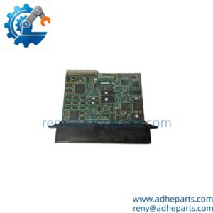
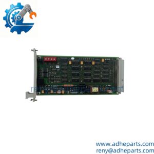
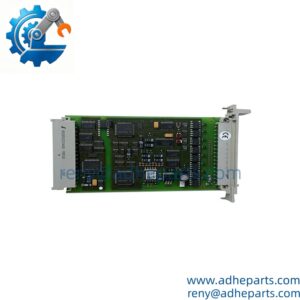
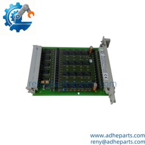
In a safety-related control system, a digital output module must do more than switch a field device on or off. It also needs to support fault detection and maintain reliable communication with the controller. The ICS Triplex T8461C Trusted TMR Digital Output Module provides 40 monitored output channels for compatible 24/48 VDC applications, supporting field-device control within a Trusted control architecture.
Its triple modular redundant design and onboard diagnostics help the system identify output and field-circuit abnormalities. For maintenance teams supporting legacy installations, the critical purchasing step is confirming the exact suffix, hardware revision, field termination arrangement, and load requirements before selecting a replacement.
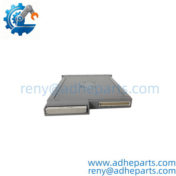
T8461C
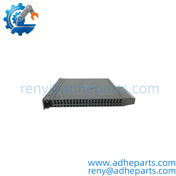
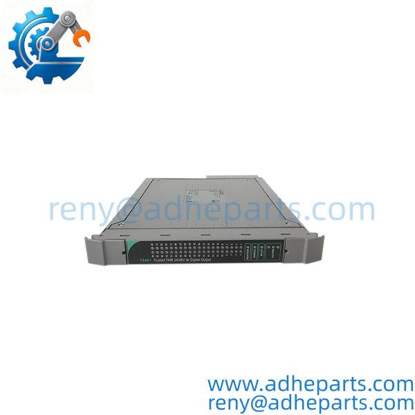
T8461C
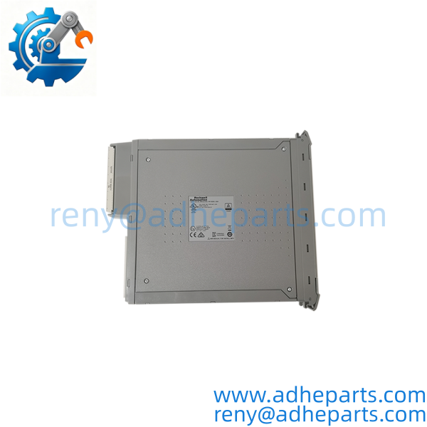
T8461C
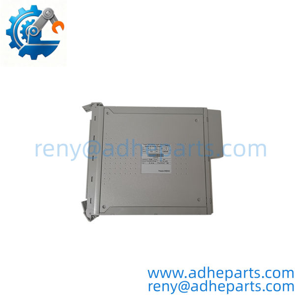
T8461C
Key Technical Specifications
| Parameter | Specification |
|---|---|
| Model | T8461C |
| Manufacturer | ICS Triplex |
| Product Family | Trusted TMR |
| Module Type | Digital Output Module |
| Output Channels | 40 |
| Output Architecture | Triple Modular Redundancy (TMR) |
| Nominal Field Voltage | 24/48 VDC applications |
| System Supply Voltage | 20–32 VDC |
| Operational Field Voltage Range | Approximately 18–60 VDC |
| Output Current | Up to 0.75 A per channel, subject to load and group limits |
| Output Grouping | Five groups of eight channels |
| Maximum Group Current | Reported as 6 A per group; verify the applicable manual and configuration |
| Diagnostics | Output voltage/current monitoring and field-circuit fault diagnostics |
| Sequence of Events | 1 ms event resolution |
| Installation | Compatible Trusted system chassis and field termination arrangement |
| Operating Temperature | Commonly specified around 0°C to +60°C; verify the unit’s applicable documentation |
Specification note: Values above describe commonly published T8461-family specifications. Confirm the exact T8461C hardware revision and its corresponding technical manual before finalizing a design or replacement decision. Do not assume that every electrical limit applies to every revision or installation.
Field Application & Technical Pitfalls
Typical Applications
1) Safety-related shutdown and trip circuits
The T8461C can provide digital output control to compatible field circuits used in industrial protection and shutdown applications. Actual safety performance depends on the complete system design, configuration, diagnostics, and validated application—not the module alone.
2) Discrete control of relays and solenoids
Compatible loads may include interposing relays, solenoid-operated devices, and other DC field equipment. Check the device’s pickup current, steady-state current, inductive characteristics, and suppression requirements before connecting it to an output channel.
3) Legacy Trusted system maintenance
For facilities maintaining an installed Trusted platform, a verified spare can reduce the risk of extended downtime caused by a failed output module. Before purchasing, compare the installed part number, hardware revision, system configuration, and field termination assembly.
Three Replacement Pitfalls to Avoid
Pitfall 1: Treating T8461C and T8451C as interchangeable
These models are not simply alternative labels for the same specification. The T8451C is associated with 24 VDC digital output applications, while the T8461C supports 24/48 VDC applications. Confirm the full part number and required field voltage before ordering.
Pitfall 2: Checking each channel but ignoring group current
A load may be within the individual channel rating while the combined load on its power group exceeds the group limit. Calculate the expected simultaneous current draw, including startup or pickup current, and check the applicable manual for the exact grouping and ratings.
Pitfall 3: Assuming online replacement is always permitted
Live replacement depends on the Trusted system’s supported slot arrangement, field termination hardware, configuration, and site procedures. Never remove a module solely because a similar installation supports hot swapping.
Field lesson: Imagine a replacement passes a basic bench check but triggers field alarms immediately after installation. The cause may not be a defective module; a mismatch in field supply, output loading, or system configuration can produce the same symptoms. Comparing the installed unit’s label and configuration records before dispatch is usually far less expensive than troubleshooting an avoidable mismatch at the plant.
Quality Control (QC) SOP & Transparency
For the ICS Triplex , our inspection process focuses on identity, condition, and suitability for the intended application.
- Part-number verification: Check the model designation, suffix, nameplate, and available serial or revision information against the purchase requirement.
- Visual inspection: Examine the housing, connectors, backplane interface, terminal connections where applicable, and signs of impact, corrosion, contamination, or unauthorized repair.
- Configuration review: Where information is available, compare the requested module variant with the customer’s existing Trusted system and field termination arrangement.
- Functional checks: Testing is performed where an appropriate test setup and supporting documentation are available. A visual inspection alone is not represented as a complete functional test.
- Final QA and packing: Recheck the model and physical condition before packing the unit for shipment. Inspection photos or video can be provided when available and agreed upon.
Supply information
- Warranty: 12 months, subject to order confirmation
- Condition: Confirmed on the quotation and order documents
- Inspection: Photo or video inspection can be arranged where available
- Documentation: Available documents can be checked against the supplied unit
- Lead time: Confirmed according to the actual stock status and order requirements
Frequently Asked Questions
Q1: What does the ICS Triplex do?
It is a 40-channel Trusted TMR digital output module used to control compatible DC field devices within a supported Trusted control system.
Q2: Is the a digital input or communication module?
No. It is a digital output module. It should not be substituted for a digital input module, communications interface, or controller processor.
Q3: Can the operate with both 24 VDC and 48 VDC field devices?
It is intended for 24/48 VDC output applications, with commonly published operating field-voltage limits of approximately 18–60 VDC. Verify the applicable hardware documentation and the connected device’s requirements before energizing the circuit.
Q4: Can it replace an existing T8461 module?
Do not assume direct interchangeability based on the family name alone. Compare the complete part number, revision, system configuration, field termination arrangement, and application requirements before approving a replacement.
Q5: Does the support hot swapping?
Online replacement may be supported in approved Trusted configurations, such as supported companion-slot or SmartSlot arrangements. Follow the system manual and plant procedure; do not assume a standard slot permits live replacement.
Q6: Is the suitable for a safety-related application?
It is part of the Trusted TMR product family used in safety-related control architectures. Suitability for a specific safety function must be established from the system certification, application design, configuration, and applicable safety documentation. The module designation alone does not certify the complete installation.
Q7: What information should I provide when requesting a quotation?
Please provide the full model number (), required quantity, preferred condition, and any available nameplate or installed-module photos. If the unit is intended as a replacement, include the existing revision and relevant field termination or chassis information to help verify compatibility.