Description
Note: Many products are not yet listed. Please contact us for more product information. Our supply channels are constantly expanding, and we currently have 20 stable shared supply channels. Please confirm the model, product, price, and all other necessary information with customer service before placing an order. We offer new, refurbished, and used products, and prices are adjusted according to the year of the item you require.
Product Introduction
When a combined cycle gas turbine fails to detect a critical lube oil pressure interlock status change mid-run, the root cause almost always traces back to a failed contact input board that can no longer reliably read hardwired safety interlock signals.
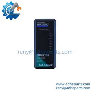
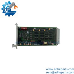
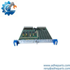
Purpose-built for the GE Speedtronic Mark VI platform, this module is the core discrete signal collection layer for gas and steam turbine power generation equipment. It natively interfaces with all hardwired field contact devices, and every channel features 1500V galvanic isolation to block electrical noise and transient surge damage. It fits directly into the Mark VI TMR control rack without requiring major system modifications.
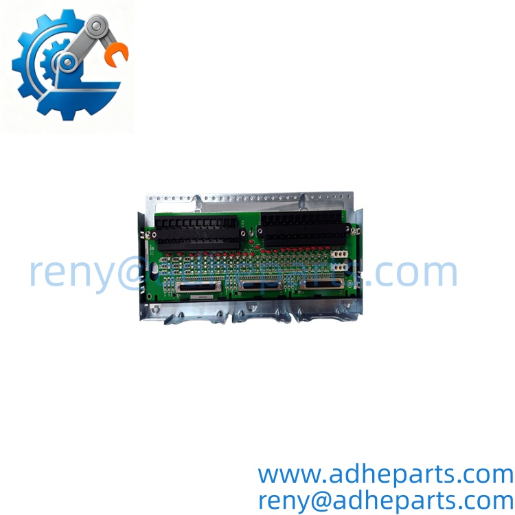
IS200TBCIH1CCD
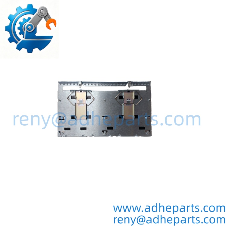
IS200TBCIH1CCD
Key Technical Specifications
| Parameter | Value |
|---|---|
| Product Name | TBCI Contact Input Terminal Board |
| Compatible Platforms | GE Speedtronic Mark VI Turbine Control System |
| Number of Input Channels | 16 isolated 24VDC contact inputs |
| Channel Isolation Rating | 1500 V AC |
| Input Signal Type | Dry contact / 24VDC wet contact |
| Operating Temperature Range | 0°C to +60°C |
| TMR Slot Compatibility | R1 / R2 / R3 triple redundant core positions |
| Country of Origin | United States |
| Net Weight | ~0.4 kg |
| HS Customs Tariff Number | 85423190 |
| Agency Approvals | CE, certified for power generation safety applications |
| Form Factor | Standard Mark VI rack single slot |
| Hot-Swap Support | Full hot-plug compatible |
Field Application & Technical Pitfalls
This part runs three non-negotiable production-critical roles.
First, it acts as the primary interlock signal collection board for combined cycle gas turbines, reading all hardwired ESD interlock statuses before the turbine is allowed to start.
Second, it collects all limit switch and valve position feedback signals for large utility steam turbines, ensuring the control system has full visibility of every actuator’s actual position.
Third, it serves as the discrete input interface for refinery mechanical drive gas turbines, delivering clean contact status signals to the main control system even under high electrical noise conditions.
⚠️ Debounce Time Configuration Mismatch Risk: Every channel has independent configurable input debounce time. If you set the debounce time too short, electrical noise will trigger false status changes that cause unplanned turbine trips.
⚠️ Field Contact Wetting Current Mismatch: The module provides 24VDC wetting current for dry contact inputs. If you connect a field contact with very high contact resistance, the module will fail to detect the closed state reliably.
⚠️ TMR Slot Position Mismatch: This board must be seated in the exact corresponding R1/R2/R3 TMR core slot. If you install it in the wrong slot, the Mark VI system will not recognize the board, and all corresponding interlock signals will be marked as invalid.
I watched a senior turbine tech skip the debounce time configuration last summer. He swapped this board into a 200MW gas turbine control rack, left all channels at the default 1ms debounce setting, and a nearby VFD switching noise triggered a false lube oil pressure interlock trip. The turbine tripped offline unexpectedly, and the plant lost 2 hours of generation revenue while they restarted the unit. That 1-minute configuration oversight forced the operations team to perform a full turbine restart sequence that took 90 minutes to complete.
Quality Control (QC) SOP & Transparency
- Inbound Verification: Cross-check the OEM serial number against GE’s official Mark VI part revision database, run anti-counterfeit validation on the board’s laser-etched serial label, and confirm no prior rework traces on the input signal circuit solder joints.
- Live Rig Testing: Seat the board in a certified Mark VI test rack, connect a calibrated 24VDC contact simulator, and verify full 16-channel stable status detection across 4 hours of continuous operation.
- Parameter Testing: Perform 1800V AC 60-second dielectric withstand test across all signal channels and chassis ground, confirm every channel detects contact closure and opening correctly, and log all debounce time response data.
- Final QA & Packaging: Seal the fully tested board in a static-shielding anti-static bag, apply a unique QC passed serial label, and pack it in ESD-dissipative foam with a printed hard copy of the full input function test report.
Frequently Asked Questions
- Can I hot-swap this board while the Mark VI rack is powered on? Yes, it supports full hot-plug. But you must put all corresponding interlock loops into full bypass mode before removing the board, otherwise you will trigger an unplanned turbine trip.
- What exact GE turbine control systems does this part work with? It is fully compatible with all GE Speedtronic Mark VI systems. It will not establish stable communication with older Mark V or newer Mark VIe platforms.
- How long is the standard warranty for this new surplus unit? It carries a full 12-month functional warranty. If it fails within that window under specified operating conditions, we cover all return shipping and bench replacement costs.
- How do I tell a genuine OEM unit apart from a refurbished clone? Genuine units have the GE Fanuc hologram sticker on the side of the PCB, and every input channel uses a precision 0.1% tolerance current limiting resistor. Refurbished clones usually skip the official hologram and use generic 1% tolerance resistors that drift after 2 years of operation.
- Will this IS200TBCIH1CCD directly replace an older Mark VI contact input board? No. Older TBCI variants have different default debounce time settings. You will need to reconfigure every channel’s debounce time in the Mark VI control software after swapping.
- What’s the maximum safe continuous operating temperature at full 16-channel load? It will hold stable contact detection performance up to 60°C, though your mileage may vary if the rack cooling airflow drops below 15 CFM and internal component temperatures spike 15°C above ambient.