Description
Note: Many products are not yet listed. Please contact us for more product information. Our supply channels are constantly expanding, and we currently have 20 stable shared supply channels. Please confirm the model, product, price, and all other necessary information with customer service before placing an order. We offer new, refurbished, and used products, and prices are adjusted according to the year of the item you require.
Key Technical Specifications
| Parameter | Technical Specification |
|---|---|
| OEM Part Number | 1C31222G01 |
| Manufacturer | Emerson / Westinghouse |
| System Platform | Ovation DCS |
| Module Type | KUEP Relay Output Base Assembly |
| Number of Channels | 12 |
| Relay Technology | Electromechanical KUEP-style relays |
| Compatible Electronics Module | 1C31219G01 |
| Form C Contact Rating | 10 A @ 240 VAC, PF = 0.8; 3 A @ 150 VDC |
| Form X Contact Rating | 10 A @ 240 VAC, PF = 0.8; 10 A @ 150 VDC |
| Dielectric Isolation | 2,200 V AC/DC, relay contacts to logic |
| Typical Relay Operate Time | 15 ms, excluding contact bounce |
| Typical Relay Release Time | 10 ms, excluding contact bounce |
| Auxiliary Supply | 25 V typical; maximum varies by relay configuration |
| Operating Temperature | 0–45°C for Form C kit; 0–60°C for Form X kit |
| Storage Temperature | Form C: -40 to 50°C; Form X: -40 to 70°C |
Important configuration detail: The 1C31222G01 is the KUEP relay base, not a standalone logic module or a personality module. Its contact arrangement is determined by the installed relay kit. Form C and Form X versions have different DC current ratings and terminal arrangements, so the relay kit must be identified before replacement.
Product Introduction
The Emerson 1C31222G01 is a 12-channel KUEP-style relay output base designed for the Ovation Distributed Control System. It provides the physical relay mounting and field-terminal interface used to switch AC and DC loads in industrial control applications. The base works with the 1C31219G01 Relay Output Electronics Module, which interfaces the relays with the Ovation I/O controller.
Its key selection factor is the installed relay contact configuration. Depending on the project-specific relay kit, the base supports Form C or Form X contacts, with different DC load ratings. Confirming the relay kit and field wiring arrangement is essential before ordering a replacement.
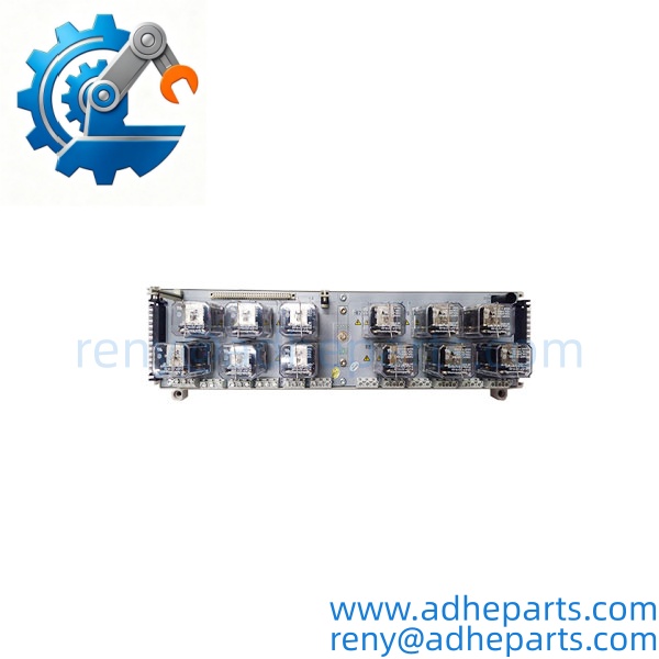
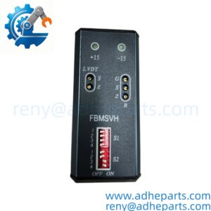
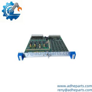
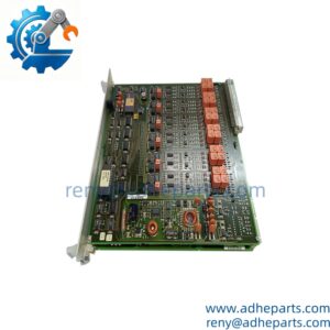
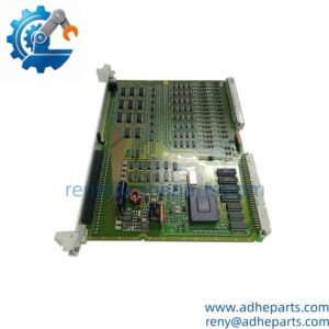
1C31222G01
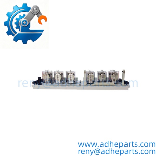
1C31222G01
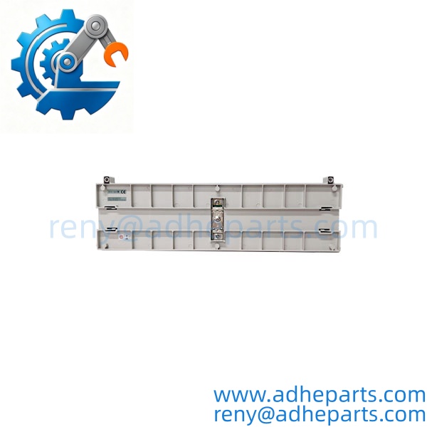
1C31222G01
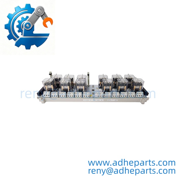
1C31222G01
Application Scenarios & Field Experience
Relay output assemblies are used where DCS logic must operate discrete field loads through electromechanical contacts. A mismatch in contact form, voltage rating, or current rating can cause incorrect switching or premature contact failure. The 1C31222G01 is particularly relevant when maintaining existing Ovation systems that use the 12-channel KUEP relay arrangement.
1. Power Generation – Auxiliary Equipment Control
Relay outputs can switch control circuits for pumps, fans, and other auxiliary equipment. The appropriate contact configuration must match the load voltage and current.
2. Steam and Boiler Systems – Solenoid Valve Control
Discrete relay contacts can operate solenoid-valve control circuits used in boiler and steam auxiliary processes. The Form C or Form X arrangement must match the required field wiring.
3. Water Treatment – Pump and Alarm Switching
Relay outputs can provide discrete switching signals for pump control circuits, alarm devices, and interlock systems integrated with the Ovation DCS.
4. Industrial Utilities – Contactor and Interlock Circuits
The relay base can be used in control circuits for contactors and equipment interlocks, provided the actual load remains within the specified contact ratings.
Illustrative engineering scenario, not a documented customer installation.
A plant experiences intermittent switching in one of its Ovation relay output circuits. The maintenance team checks the field load, relay contacts, terminal wiring, and the installed relay kit. The investigation identifies that the replacement selection must preserve the original Form C or Form X contact arrangement. Matching the base number alone would not be sufficient to confirm the correct configuration.
Standard Operating Procedure (SOP) for Quality Control
1. Visual & Origin Inspection
- Verify the 1C31222G01 model marking and inspect the housing, terminal blocks, connectors, and relay mounting positions.
- Check for corrosion, cracked components, damaged terminals, and signs of unauthorized rework.
- Identify the installed relay kit where possible: 5A26458G01, 5A26458G02, or 5A26458G03.
- Inspect the associated 1C31219G01 electronics module separately if supplied as part of an assembly.
2. Functional & Relay Contact Testing
- Where a suitable test setup is available, verify relay coil operation and contact continuity.
- Check each channel for correct switching behavior and contact condition.
- Confirm the installed contact arrangement against the expected Form C or Form X wiring diagram.
- High-current load capacity should be verified using an appropriate test arrangement and the OEM contact ratings. A basic continuity test does not establish full load capability.
3. Firmware Verification
- Firmware verification is not applicable to the 1C31222G01 relay base assembly.
- For a complete assembly, verify the associated 1C31219G01 electronics module and the receiving Ovation system configuration.
4. ESD-Safe Packaging
- Use appropriate ESD precautions when handling the associated electronics module.
- Protect exposed connectors and terminal interfaces from impact, dust, and moisture.
- Use anti-static packaging for electronic components and suitable cushioning for the relay base.
5. Pre-Shipment Documentation
- Record the base model and identifiable relay-kit configuration.
- Provide actual product photographs upon request.
- Document the inspection scope and any functional tests performed.
- Confirm whether the quotation covers the base alone or a complete relay assembly.
Frequently Asked Questions (FAQ)
Q1: Can the 1C31222G01 replace the 1C31223G01?
A: They are not direct substitutes. The 1C31222G01 is a 12-channel KUEP-style base, while the 1C31223G01 is a 16-channel G2R-style base. Their relay arrangements and terminal configurations differ. Check the installed system design and field wiring before considering any alternative.
Q2: What warranty is provided for the 1C31222G01?
A: We offer a 12-month warranty, subject to confirmed order terms. The supplied condition and warranty coverage will be stated in the quotation and order confirmation.
Q3: Is the 1C31222G01 available for immediate shipment?
A: Availability and condition must be confirmed against current inventory. For confirmed available stock, the standard arrangement is shipment within one week after payment. Contact us with your required quantity and relay-kit configuration for a current quotation.
Q4: Does the 1C31222G01 require firmware configuration?
A: The relay base itself does not have standalone firmware. The associated 1C31219G01 electronics module and Ovation controller configuration determine the relay output operation. Verify the configured channel assignments and communication timeout settings as part of system commissioning.
Q5: What should engineers check before installing this relay base?
A: Confirm the relay kit, contact form, load voltage, current rating, and terminal wiring. Also check the auxiliary power arrangement: the OEM manual specifies a 25 V typical auxiliary supply and describes a required return-connection arrangement using the 5A26471G01 jumper module or the appropriate cable assembly. Follow the approved cabinet wiring and grounding instructions. Isolate the relevant circuits before installation and verify the complete output path before returning the equipment to service.