Description
Note: Many products are not yet listed. Please contact us for more product information. Our supply channels are constantly expanding, and we currently have 20 stable shared supply channels. Please confirm the model, product, price, and all other necessary information with customer service before placing an order. We offer new, refurbished, and used products, and prices are adjusted according to the year of the item you require.
Product Introduction
The 1746‑OW16 is a widely deployed legacy relay‑output I/O module built for the SLC 500 controller family. Mechanical relay contacts allow direct switching of both AC and DC field devices without external interposing relays, which simplifies panel wiring for motor starters, indicator lamps, solenoid valves and auxiliary contactors.
Since OEM manufacturing has ended, this part is primarily used for existing‑plant spare‑part replenishment and emergency replacement of failed SLC‑system hardware. Relay contact wear is the dominant failure mode over long service life; load type and in‑rush currents heavily dictate service cycle life. For new green‑field deployments, platform migration planning is strongly recommendedRockwell A….
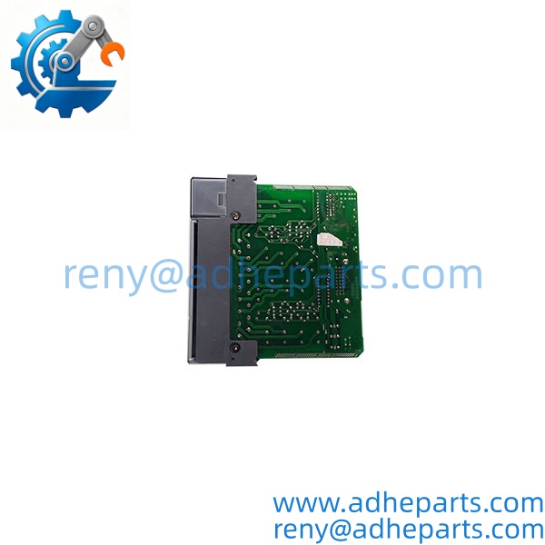
1746‑OW16
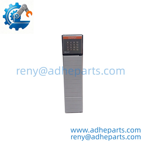
1746‑OW16
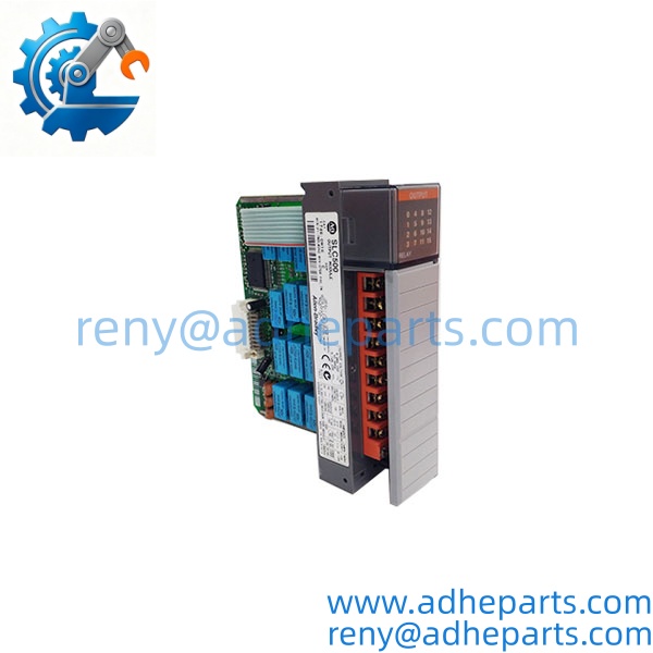
1746‑OW16
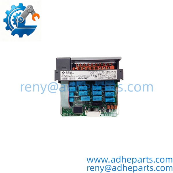
1746‑OW16
Key Technical Specifications
| Parameter | Value |
|---|---|
| Platform | SLC 500 Chassis‑mount I/O, Bulletin 1746 |
| Number of Outputs | 16 mechanical relay outputs; 8 points per common |
| Load Voltage Range | 5‑265 V AC; 5‑125 V DCRockwell A… |
| Max Current per Point | 2 A resistive |
| Max Current per Common | 8 A |
| Total Module Max Current | 16 A AC aggregate |
| Backplane Draw | 170 mA @ 5 VDC; 180 mA @ 24 VDClishengaut… |
| Response Delay | Max 10 ms ON; Max 10 ms OFF |
| Isolation | 500 VDC between backplane logic and field circuitsRockwell A… |
| Operating Ambient Temp | 0 °C … +60 °C (32 °F … 140 °F)ManualsLib |
| Storage Temperature | ‑40 °C … +85 °C |
| Operating Humidity | 5‑95 % non‑condensing |
| Certifications | UL 508, CSA C22.2, Class I Division 2 Groups A‑D |
| Weight | 0.53 kg |
| Lifecycle Status | Discontinued 24‑Nov‑2022, engineering replacement only, no new factory buildsRockwell A… |
Field Application & Technical Pitfalls (The Engineer’s Guide)
Critical Industrial Scenarios
- Batch‑processing plants: driving local status indicator lights, auxiliary solenoids, and small contactor coils on SLC‑500 controlled production lines.
- Water‑wastewater facilities: legacy pump‑station control where mixed‑voltage field devices share one PLC chassis.
- Material‑handling systems: conveyor auxiliary outputs, gate actuators and alarm annunciator circuits on existing SLC‑based control cabinets.
Technical Pitfalls (Bold Warnings)
- ⚠️ Relay contact de‑rating for inductive loads: Published 2 A per‑point rating applies for resistive loads only. Inductive loads (solenoids, contactor coils) create arc erosion and drastically reduce contact cycle life. Always de‑rate current or fit external suppression diodes / RC snubbers across inductive loads. Un‑suppressed inductive transients will cause premature contact pitting and intermittent output dropout with no module fault indication.
- ⚠️ Power‑up transient OFF state: On backplane power loss and restoration, all relay outputs de‑energize regardless of PLC logic retentive settings. There is a 50‑250 ms window before the first PLC scan re‑asserts output states. This momentary drop can trigger unintended equipment cycling on safety‑critical loads. Use external latching relays for functions that cannot tolerate brief OFF pulses during power recovery.
- ⚠️ Common‑group current limit violation: Outputs are grouped into two banks of 8 points sharing common terminals. Do not exceed 8 A continuous for each common bank, even if individual channel loads stay below 2 A. Over‑current on a common rail causes over‑heating, terminal discoloration and latent module damage without blowing internal fuses.
- ⚠️ No per‑channel diagnostic feedback: This module provides no individual relay‑contact health feedback to the PLC processor. Worn‑out or welded relay contacts produce wrong field‑device behavior without generating fault bits in the controller image table. Field‑side feedback inputs are required to validate actual load status.
Real‑world field anecdote: A food‑processing facility replaced a failed 1746‑OW16 during night shift maintenance. Technicians wired multiple contactor coils directly to relay outputs and skipped RC‑snubber installation. Within six months, multiple channels began showing random intermittent failures. Visual inspection found heavy arc‑pitting on relay contact surfaces; adding external snubber networks prevented further premature wear on replacement hardware.
Quality Control (QC) SOP & Transparency
- Inbound Verification: Validate catalog number, series revision level and serial number against OEM label. Inspect edge‑connector gold contacts for corrosion, wear or burn marks from previous chassis faults. Inspect terminal block pins for bending, heat discoloration or tool damage. Flag units with burned‑plastic odor as prior‑fault hardware.
- Live Rig Testing: Seat module inside valid SLC‑500 chassis; apply proper backplane power. Confirm module powers‑up without fault indicators. Cycle every single relay channel repeatedly via PLC logic. Measure continuity on each output contact for consistent ON/OFF switching behavior.
- Parameter Testing: Load test sample channels with resistive load close to rated current; verify no excessive voltage drop across closed contacts. Confirm isolation resistance between backplane side and field terminals meets OEM thresholds. Check for mechanical relay‑chatter under nominal operating conditions.
- Final QA & Packaging: Re‑fit original or matching replacement terminal block. Protect gold‑plated edge connector with anti‑static cover. Seal inside static‑shield bag, apply internal QC‑passed sticker with test date and inspector ID. Package within shock‑absorbing rigid carton for transit.
Frequently Asked Questions (FAQ)
Can I use 1746‑OW16 for safety‑related interlock circuits? Not for SIL‑rated safety loops. Relay‑contact welding risk exists, and there is no built‑in channel diagnostic feedback to the PLC. Implement external safety relays and independent feedback inputs for safety functions.
What replacement options exist now that 1746‑OW16 is discontinued? For existing SLC‑500 chassis: only surplus / refurbished 1746‑OW16 units drop‑in directly. For new designs, full platform migration to newer controller families is required; no direct pin‑to‑pin drop‑in OEM replacement module exists for the SLC‑500 hardware footprintlishengaut….
What warranty coverage applies for surplus / refurbished 1746‑OW16? Twelve‑month standard warranty applies. Exclusions cover damage from inductive‑load transients, over‑current on common groups, field‑wiring short‑circuits, and normal mechanical relay‑contact wear from operational cycles.
How can I tell if unit relay contacts are already worn from heavy prior service? Visual signs include burn marks inside module housing, discoloration on terminal pins, inconsistent continuity during relay cycling, and audible noisy relay‑clicking. Bench continuity testing across all channels is mandatory for used units.
Does this module support hot‑swap while chassis is powered? SLC 500 I/O modules are not designed for hot‑swap operation. Power down chassis backplane before inserting or removing the 1746‑ to avoid edge‑connector arcing and potential module or processor damage.
Can I mix AC and DC loads on the same 1746‑ module? Yes, individual relay channels can switch AC or DC loads. Respect per‑channel and per‑common current ratings, and apply proper load‑suppression hardware for inductive loads regardless of AC or DC voltage type.