Description
Note: Many products are not yet listed. Please contact us for more product information. Our supply channels are constantly expanding, and we currently have 20 stable shared supply channels. Please confirm the model, product, price, and all other necessary information with customer service before placing an order. We offer new, refurbished, and used products, and prices are adjusted according to the year of the item you require.
3. Product Introduction (Anti-Template)
Legacy DF1 devices still sit on many plant floors next to newer Modbus Plus networks. The 4301-MBP-DFCM bridges those two worlds without forcing a full network redesign.
It mounts on a standard DIN rail, presents one Modbus Plus port and a configurable DF1 serial port, and moves data in either direction as Master or Slave. Maintenance teams keep this gateway on the shelf because a failed protocol converter can isolate an entire group of drives or PLCs until a replacement is installed.
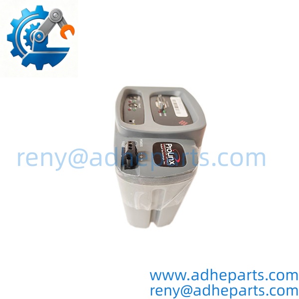
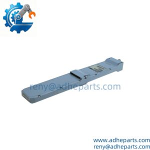
4301-MBP-DFCM
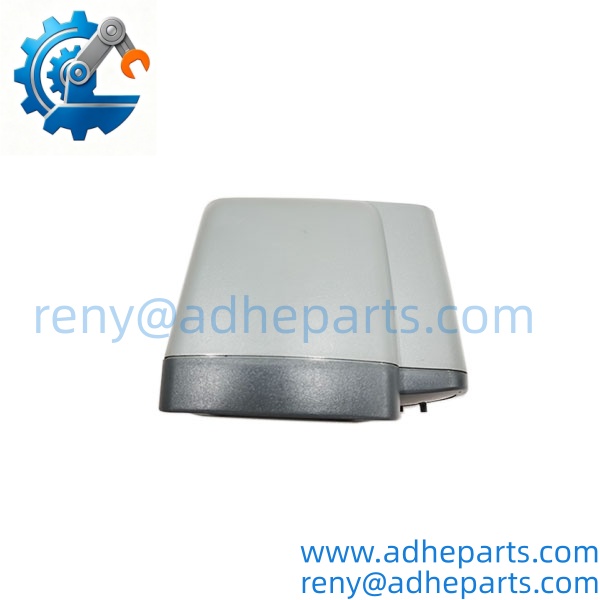
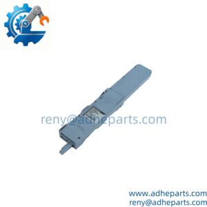
4301-MBP-DFCM
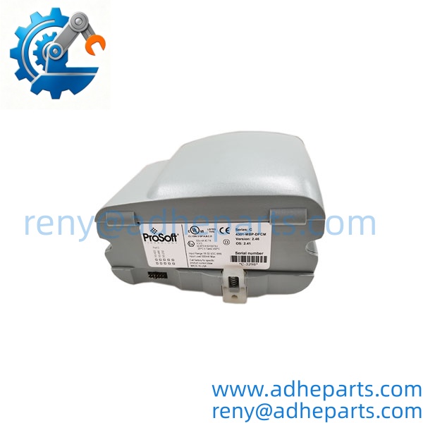
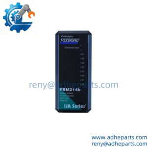
4301-MBP-DFCM
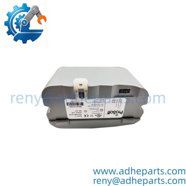
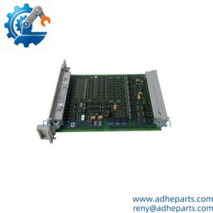
4301-MBP-DFCM
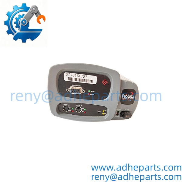
4301-MBP-DFCM
4. Key Technical Specifications
| Parameter | Value |
|---|---|
| Primary Function | Modbus Plus ↔ DF1 Protocol Gateway |
| Modbus Plus Port | Configurable DB-9F (Master or Slave) |
| DF1 Port | Configurable serial (Master or Slave, full- or half-duplex) |
| Power Supply | 24 VDC nominal (typical 18–36 VDC range) |
| Mounting | DIN-rail (standalone) |
| Configuration | Non-volatile memory; PC-based software |
| Operating Temperature | Approximately –20 °C to +50 °C (model dependent) |
| Typical Applications | Integration of Allen-Bradley DF1 devices into Modbus Plus systems |
5. Field Application & Technical Pitfalls (The Engineer’s Guide)
This gateway commonly links older Allen-Bradley SLC or PLC-5 equipment running DF1 into a Modbus Plus backbone used by Quantum or other Modbus Plus masters. It also appears in hybrid systems where a single DF1 drive or panel must report data upstream without adding a full network interface card.
Three pitfalls appear during replacement:
Port role mismatch – both the Modbus Plus and DF1 sides must be set correctly as Master or Slave; reversing the roles produces silent data loss.
Baud rate and parity errors – DF1 serial settings must exactly match the connected device; a single mismatch stops all traffic.
Node address conflicts – on the Modbus Plus side the gateway occupies a unique node address; duplicating an existing address takes the entire segment offline.
One plant installed a replacement unit and saw intermittent DF1 timeouts. The serial port had been left at the default baud rate while the field device ran at 19.2 k; correcting the configuration restored steady communication within minutes.
6. Quality Control (QC) SOP & Transparency
- Inbound Verification – OEM labeling, serial number, and date codes are photographed and checked against the packing list; any signs of prior field use are noted.
- Live Rig Testing – unit is powered at 24 VDC, configured with test Modbus Plus and DF1 traffic, and verified for bidirectional data movement and LED status.
- Parameter Testing – port isolation, command list execution, and error handling are confirmed under load.
- Final QA & Packaging – unit is sealed in an anti-static bag with desiccant, fitted with a QC-passed label showing test date and technician ID, then double-boxed for shipment.
7. Frequently Asked Questions (FAQ)
Can the DF1 port be set as either Master or Slave?
Yes. Each port is independently configurable for Master or Slave operation.
Does this gateway require a backplane or PLC slot?
No. It is a standalone DIN-rail device and does not occupy a PLC chassis slot.
What power supply does it need?
Nominal 24 VDC. Confirm the exact allowable range on the unit label before applying power.
Is configuration retained after power loss?
Yes. Configuration is stored in non-volatile memory on the module.
What warranty comes with a new-surplus unit?
Twelve months from shipment against defects in materials and workmanship when installed within the published ratings.
How do I confirm the gateway is healthy after installation?
Apply power, verify the status LEDs, establish communication on both the Modbus Plus and DF1 sides with known-good devices, and confirm that data values update in both directions without error counters incrementing.