Description
Note: Many products are not yet listed. Please contact us for more product information. Our supply channels are constantly expanding, and we currently have 20 stable shared supply channels. Please confirm the model, product, price, and all other necessary information with customer service before placing an order. We offer new, refurbished, and used products, and prices are adjusted according to the year of the item you require.
Product Introduction
Generator paralleling requires accurate electrical measurements and reliable coordination between the generator, busbar, and circuit breaker. The DEIF SCM4-2 combines three-phase measurement with synchronization and generator-control functions within the Delomatic 4 control architecture. It evaluates electrical quantities used by the control system to support synchronization and related switching operations.
Compared with the SCM4-1, the SCM4-2 adds governor and automatic voltage regulator (AVR) control capabilities. Depending on the installed configuration, these interfaces can support speed and excitation regulation through binary or analog outputs. For marine power systems and industrial generator installations, preserving the original module configuration is essential when replacing a failed unit.
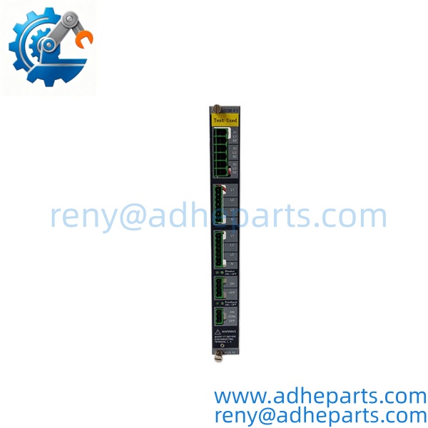
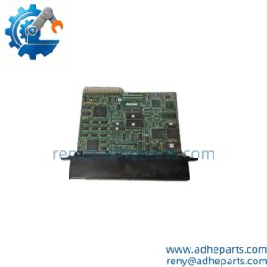
SCM4-2
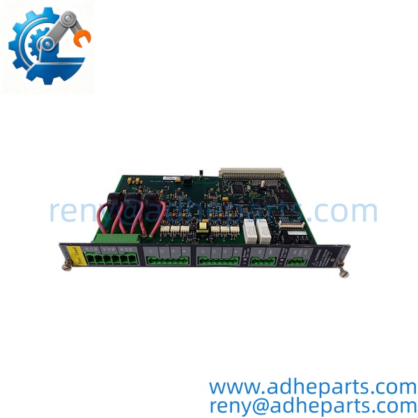
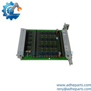
SCM4-2
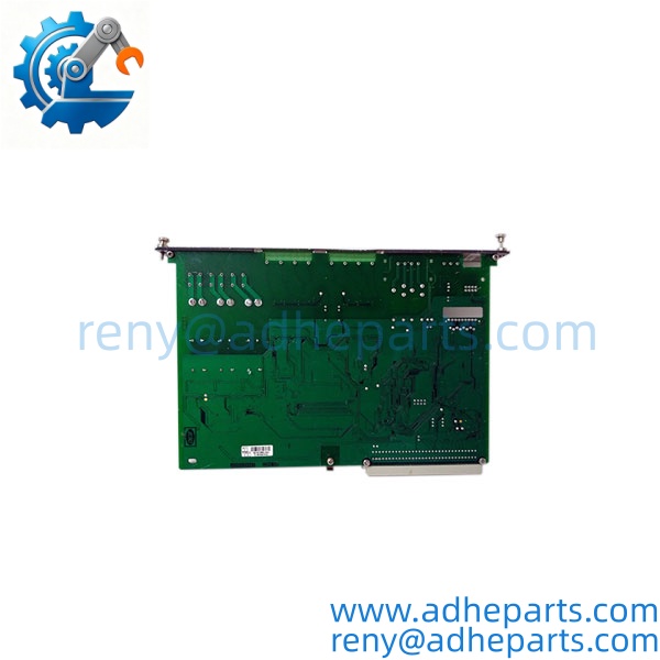
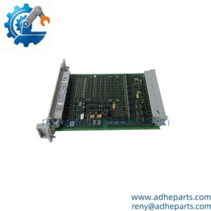
SCM4-2
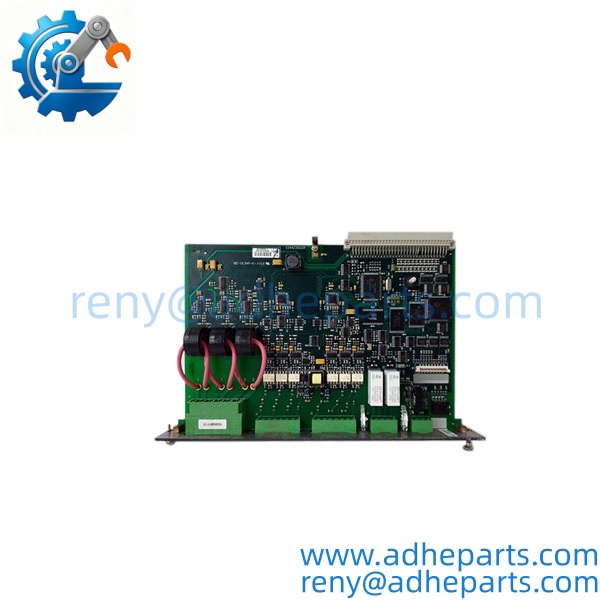
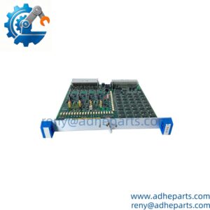
SCM4-2
Key Technical Specifications
| Parameter | Specification |
|---|---|
| Manufacturer | DEIF |
| Model | SCM 4-2 / SCM4-2 |
| System | Delomatic 4 (DM-4) |
| Product Type | Synchronizing, control, and measurement module |
| Module Width | 60.96 mm (12 TE) |
| System Power Supply | Supplied by the PCM module through the backplane |
| Typical Power Consumption | 2 W |
| Maximum Power Consumption | 3 W |
| Current Measurement Inputs | One three-phase current input |
| Voltage Measurement Inputs | Two three-phase voltage inputs |
| Current Input Range | 1 A or 5 A AC secondary, depending on configuration |
| Voltage Measurement Range | 100–690 VAC, phase-to-phase, ±20% |
| Measurement Method | True RMS |
| Measurement Accuracy | Class 0.5 |
| Frequency Measurement Range | 30–70 Hz |
| Harmonic Measurement | Up to 500 Hz |
| Nominal Ambient Temperature | -10°C to +55°C |
| Operational Temperature Range | -25°C to +70°C |
| Storage Temperature | -40°C to +70°C |
| Protection Rating | IP20 |
| Mounting | Delomatic 4 rack / backplane system |
Configuration note: The SCM4-2 consists of two cards connected by a wired bus on the front side. Its governor and AVR output arrangements may differ depending on whether binary or analog interfaces are used. Verify the original unit and system documentation before ordering or commissioning a replacement.
Field Application & Technical Pitfalls
Application Scenarios
1) Generator-to-bus synchronization
The SCM4-2 supports synchronization functions used when connecting a generator to a live busbar. Voltage, frequency, and phase-related measurements provide information needed by the Delomatic control system to determine whether synchronization conditions are satisfied.
2) Generator speed and voltage regulation
The module adds governor and AVR control functions to the -1 measurement and synchronization architecture. Depending on the installed interface configuration, it can support commands for engine speed regulation and generator excitation control.
3) Marine and industrial power management
In generator-based power systems, including marine installations and industrial plants, the -2 forms part of a larger control and protection arrangement. A correctly configured spare can help restore the original system without replacing the complete generator-control architecture.
Three Replacement Pitfalls to Avoid
Pitfall 1: Confg with -1
The -d share part of their architecture, bue includes an additional engine-control card and governor/AVR functionality. Confirm the full model designation rather than selecting a module based only on its measurement and synchronization functions.
Pitfall 2: Overlooking the internal output-board configuration
e can use OPR-1 relay boards for binary governor or AVR interfaces. These boards are not required in the same way for analog-interface configurations. Before replacement, check the existing OPR-1 arrangement and the eight-wire connection between the two cards.
Pitfall 3: Failing to preserve the original settings
DEIF replacement instructions specify that the replacement unit must be assigned the same I/O address as the unit being replaced. Jumper settings and the rotation switch must also be checked. Incorrect addressing or configuration can prevent the replacement from operating correctly within the existing system.
Field example: A replacement module may fit the rack but fail to deliver the expected governor or AVR control signals because the original unit used a different output arrangement. Checking the internal boards, address settings, and interface type before installation can reduce commissioning delays.
Synchronization and Protection Considerations
Before returning the system to service, verify the current-transformer ratios, voltage-transformer connections, phase sequence, synchronization settings, breaker-control wiring, and governor/AVR interface. The relevant settings must match the approved system design.
Do not use a successful power-up test as proof that synchronization is safe. Synchronization and breaker-closing functions must be tested under approved commissioning procedures by qualified personnel.
Quality Control (QC) SOP & Transparency
- Model verification: Confire designation and record the product label and any available order or revision information.
- Physical inspection: Examine the module housing, rack connector, terminals, circuit boards, and front-side interconnection for visible damage or corrosion.
- Configuration inspection: Check the I/O address, jumper positions, rotation switch, and installed OPR-1 relay boards where applicable.
- Condition confirmation: Identify the offered unit as new original, new surplus, or refurbished based on the actual stock.
- System compatibility review: Verify the Delomatic 4 configuration, PCM module, rack arrangement, and governor/AVR interface requirements.
- Functional testing: Where a compatible test setup is available, perform the agreed measurement, control-output, and functional checks. Do not claim full synchronization testing unless it has actually been completed.
- Inspection evidence: Provide available label photographs, internal configuration photographs where appropriate, and a record of the tests performed.
- Protective packaging: Protect the electronic boards and rack connector against electrostatic discharge and transit damage.
A one-year warranty may be offered subject to the confirmed order terms. Confirm stock condition, testing scope, and dispatch lead time for the specific unit quoted.
Frequently Asked Questions
Q1: What is theF used for?
It is a Delomatic 4 module used for electrical measurement, generator synchronization, circuit-breaker control, and governor/AVR control functions.
Q2: What is the difference between -d ?
e builds on thM4-1 measurement and synchronization architecture by adding governor and AVR control capability. The two models should not be treated as interchangeable without checking the application requirements.
Q3: What current and voltage inputs doee support?
The documented measurement architecture includes one three-phase current input and two three-phase voltage inputs. Current inputs are configured for 1 A or 5 A secondary, while the documented phase-to-phase voltage range is 100–690 VAC ±20%.
Q4: Doee require a separate DC power supply?
The technical specifications state that the module receives its supply from the PCM module through the backplane. Verify the applicable Delomatic 4 configuration and wiring documentation before installation.
Q5n ree directly?
Not as a general rulee adds engine-control hardware and may include different governor/AVR output arrangements. Confirm the original system configuration before selecting a replacement.
Q6: What should be checked when replacine ?
Follow the DEIF replacement procedure. In particular, preserve the original I/O address, verify jumper and rotation-switch settings, check the two-card interconnection, and confirm the installed OPR-1 boards where applicable.
Q7: What information should I provide for a quotation?
Provide the complete model designation, required quantity, preferred condition, and photographs of the front label and installed module. If possible, include the Delomatic 4 system configuration and details of the governor/AVR interface to help verify compatibility before shipment.