Description
Note: Many products are not yet listed. Please contact us for more product information. Our supply channels are constantly expanding, and we currently have 20 stable shared supply channels. Please confirm the model, product, price, and all other necessary information with customer service before placing an order. We offer new, refurbished, and used products, and prices are adjusted according to the year of the item you require.
3. Key Technical Specifications
Confirm each line against the OEM datasheet and the marking on your existing module before ordering. Contact ratings vary with load type.
| Parameter | Value |
|---|---|
| Model | 1762-OW16 |
| Brand | Allen-Bradley |
| Product Family | MicroLogix 1200 / 1400 expansion I/O (1762) |
| Module Type | Digital relay output |
| Output Points | 16 (two groups of 8) |
| Output Type | Relay, Form A (normally open) |
| Contact Rating (Resistive) | 2 A at 250V AC / 2 A at 30V DC per point — verify |
| Contact Rating (Inductive) | Verify with OEM datasheet — derate for inductive loads |
| Minimum Load | Verify — relay contacts may not switch reliably below a minimum current |
| Total Module Current Limit | Verify — the module has a maximum combined current across all outputs |
| Isolation | Field side to backplane — verify isolation voltage |
| Backplane Current (5V DC) | Verify with OEM datasheet |
| Backplane Current (24V DC) | Verify with OEM datasheet |
| Compatible Controllers | MicroLogix 1100, 1200, and 1400 — verify controller model and firmware |
| Chassis / Expansion | Plugs into the controller’s expansion port — verify cable part number |
| Terminal Block | Removable — verify spare part number |
| Status Indicators | One LED per output point plus module status — verify arrangement |
| Operating Temperature | 0 °C to +55 °C (verify for your enclosure) |
| Storage Temperature | –40 °C to +85 °C |
| Humidity | 5% – 95% RH, non-condensing |
| Weight | Verify with OEM datasheet |
| Certifications | UL 508, CSA C22.2, CE — verify on the unit label |
4. Product Introduction
The Allen-Bradley 1762-OW16 is a sixteen-point relay output module for the MicroLogix 1200 and 1400 platforms. It switches discrete field loads — contactor coils, solenoid valves, indicator lamps, and small motor starters — and connects to the controller through the 1762 expansion bus. The outputs are relay contacts, not solid-state, so the module can switch both AC and DC loads on the same card.
The engineering value is that flexibility. A solid-state output module is tied to one voltage type and often to one polarity. The relay outputs on the 1762-OW16 let you mix a 120V AC pilot light and a 24V DC solenoid on the same module without a separate interface relay for each. In my experience, that reduces panel wiring and the spare parts inventory you have to carry.
One thing to verify before you order: the contact rating against the actual load. Relay contacts that switch a resistive load at 2A may not survive an inductive load at the same current. Check the OEM derating curve for the load type you are switching.
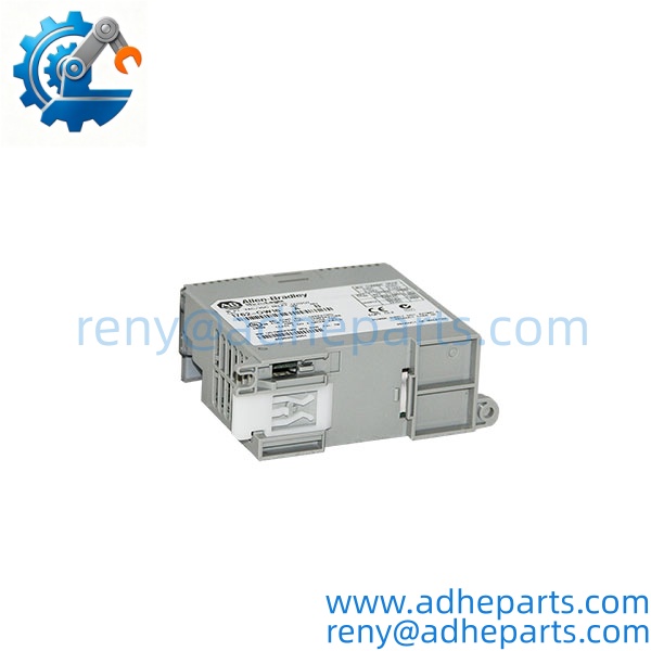
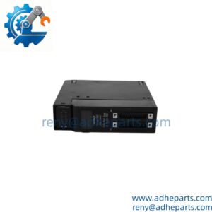
1762-OW16
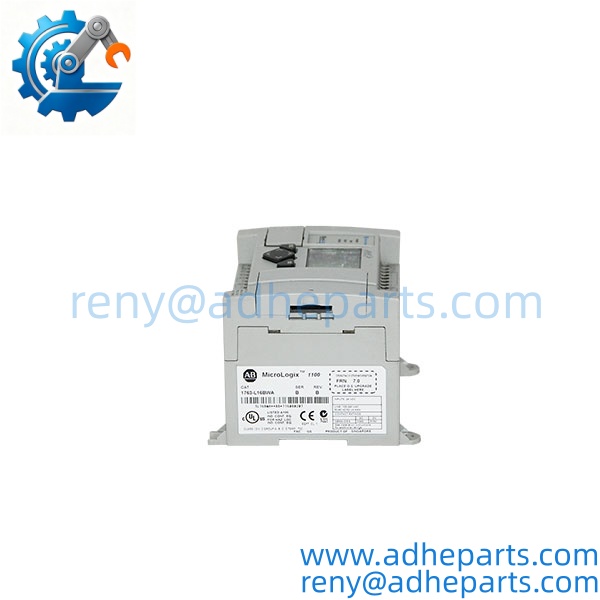
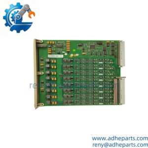
1762-OW16
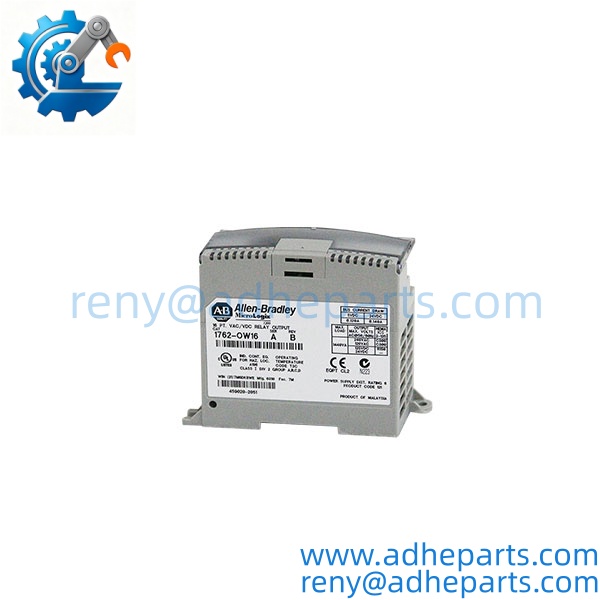
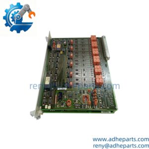
1762-OW16
5. Application Scenarios & Field Experience
Part 1 – Narrative Paragraph
The failure that shows up most on relay output modules is a contact that welds closed. The output stays on, the field device stays energized, and nobody notices until the process does something it should not. I have seen that on a conveyor where a relay output stuck on and the motor starter stayed engaged after the controller dropped the command. The cause is usually an inductive load — a contactor coil or a solenoid — that was switched at a current above what the contact was rated to break. The module was correctly installed and correctly wired; it was simply underrated for the load. Check the derating curve before you assume the module is at fault.
Part 2 – Numbered List (Application Scenarios)
- Packaging Machinery – Solenoid and Contactor Control – The module drives solenoid valves and small contactor coils on a form-fill-seal line. The relay contacts handle both the AC pilot devices and the DC solenoids without separate interface relays.
- Material Handling – Conveyor and Diverter Control – Used on MicroLogix-controlled conveyors to switch motor starters and diverter actuators. The 16 outputs cover a full zone on one module, keeping the panel compact.
- Water Treatment – Pump and Valve Control – Drives pump starter coils and actuated valve solenoids. The relay outputs tolerate the inrush of a small motor starter better than a solid-state output would.
- Building Automation – Lighting and Damper Control – Switches lighting contactors and damper actuators. The AC contact rating handles 120V and 240V circuits directly.
Part 3 – Short Field Story
A bottling plant in the Midwest had a case conveyor that would not stop when the photo-eye commanded it. The crew had replaced the photo-eye and the motor starter and the conveyor kept running. We asked them to measure the voltage at the output module with the command off. The output read 120V AC — the relay contact had welded closed. The load was a contactor coil with an inrush current higher than the contact was rated to break, and after a few thousand cycles the contacts stuck. We supplied a module with the correct contact rating for the load, and the conveyor went back to stopping on command. The original module had been correctly installed — it was underrated for the inductive load.
6. Standard Operating Procedure (SOP) for Quality Control
- Visual & Origin Inspection – We verify the Allen-Bradley marking, the 1762-OW16 catalog number, and the date code. We inspect the expansion connector for bent pins and the terminal block header for cracked plastic. A module with a damaged connector or evidence of moisture ingress is rejected.
- Revision Documentation – We read and photograph the full catalog number, the series letter, and the date code. That record ships with the module so you can compare it against the unit you are replacing.
- Controller Fit Verification – Each module is connected to a MicroLogix test controller to confirm the expansion bus engages and the controller recognizes the module type.
- Output Channel Verification – We command each of the 16 outputs to close and open, verifying contact continuity with a meter. A channel that does not change state is rejected.
- Contact Resistance Check – We measure the closed-contact resistance on each output. A reading above the OEM limit indicates a worn or pitted contact, and the module is rejected.
- Isolation Test – We apply the rated isolation voltage between the field terminals and the backplane. Leakage current must stay below the datasheet limit.
- LED Verification – We confirm each of the 16 point LEDs illuminates when its output is commanded on. A module with a dead LED passes the electrical test but gives the operator no field indication.
- ESD-Safe Packaging – The module is wrapped in anti-static film, seated in a conductive foam insert with the connectors protected, and packed in a double-wall carton with static warning labels.
7. Frequently Asked Questions (FAQ)
Q1: Can I mix AC and DC loads on the same 1762-OW16 module?
A: Yes. The outputs are relay contacts, so each point can switch an AC or DC load independently. This is the main advantage of the relay output module over a solid-state module. But verify the total module current limit — the combined current across all 16 outputs has a maximum that may be lower than 16 times the per-point rating.
Q2: What load types can the relay contacts switch?
A: The contacts are rated for resistive loads at 2A per point, but inductive loads like contactor coils and solenoids have an inrush current that can be several times the steady-state current. Check the OEM derating curve for the load type you are switching. An underrated relay will weld closed or fail prematurely.
Q3: Will this module work with my MicroLogix 1100?
A: The 1762 I/O family is designed for the MicroLogix 1200 and 1400 controllers. The MicroLogix 1100 has its own onboard I/O and does not support the 1762 expansion bus in the same way. Verify your controller model before ordering. If you send us the controller model and firmware revision, we can confirm compatibility.
Q4: What is the warranty on this module?
A: We offer a 12-month warranty from the ship date. It covers relay contact failure, backplane communication failure, and connector failure under normal operating conditions. It does not cover damage from overloading the contacts beyond their rating, ESD damage from handling without a wrist strap, or physical damage to the expansion connector. Every module is tested on a live MicroLogix chassis before it ships.
Q5: Any installation pitfalls I should watch for?
A: Four. First, power down the controller before connecting or disconnecting the expansion cable — the 1762 bus is not hot-swap capable. Second, verify the contact rating against the actual load, especially for inductive devices. Third, label the field wiring before you remove the terminal block; the block is removable but the wires are not labeled unless you label them. Fourth, after the swap, command each output and verify the field device responds before you return the machine to production. A module that powers up is not necessarily switching correctly.