Description
Note: Many products are not yet listed. Please contact us for more product information. Our supply channels are constantly expanding, and we currently have 20 stable shared supply channels. Please confirm the model, product, price, and all other necessary information with customer service before placing an order. We offer new, refurbished, and used products, and prices are adjusted according to the year of the item you require.
Key Technical Specifications
| Parameter | Specification |
|---|---|
| Manufacturer | Allen-Bradley / Rockwell Automation |
| Catalog Number | 1756-RM/A |
| Product Family | ControlLogix |
| Module Type | Redundancy Module |
| Series | A |
| Primary Function | Enhanced controller redundancy |
| Communication Interface | Dual LC single-mode fiber connection |
| Chassis Position | Any compatible chassis slot; normally installed close to the controller |
| Slot Width | 1 slot |
| Compatible Chassis | 1756-A4, 1756-A7, 1756-A10, 1756-A13, 1756-A17 |
| Supported Controller Families | ControlLogix 5560 and 5570 |
| Standard Power Supplies | 1756-PA72, 1756-PA75, 1756-PB72, 1756-PB75 |
| Redundant Power Supplies | 1756-PA75R, 1756-PB75R, 1756-PSCA2 |
| Operating Temperature | 0 to 60°C (32 to 140°F) |
| Approx. Weight | 0.29 kg (0.64 lb) |
| Connection Cable | 1756-RMC1 / RMC3 / RMC10 |
| Software / Firmware | Series A firmware versions include 2.005, 2.006, 3.002, 3.003, and 3.004 |
| Lifecycle | Discontinued / legacy |
| Installation | ControlLogix chassis-based module |
Rockwell Automation identifies the 1756-RM as a ControlLogix redundancy module and specifies one-slot installation, compatible ControlLogix chassis, controller families, power supplies, and 1756-RMC fiber cables. The Product Compatibility and Download Center identifies the Series A 1756-RM as discontinued and lists firmware versions through 3.004.
Product Introduction (Anti-Template)
Operating as the redundancy link between paired ControlLogix chassis, the Allen-Bradley 1756-RM/A helps maintain synchronized primary and secondary controller systems and supports controlled system switchover. The Series A module uses dual LC single-mode fiber connections and occupies one ControlLogix chassis slot. It is a legacy component, so firmware revision, controller family, chassis configuration, and matching redundancy hardware should be checked before procurement. Honestly, the fiber connection and firmware match deserve as much attention as the catalog number itself.
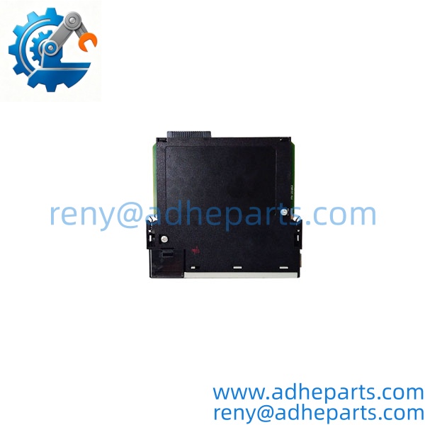
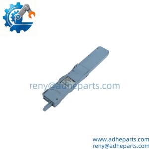
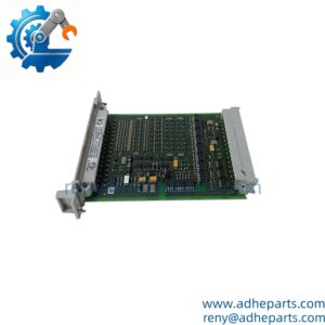
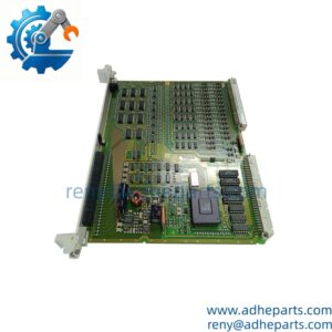
1756-RM/A
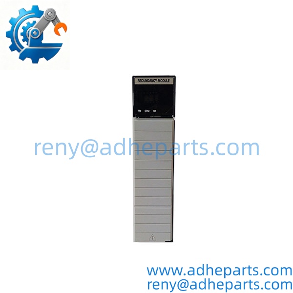
1756-RM/A
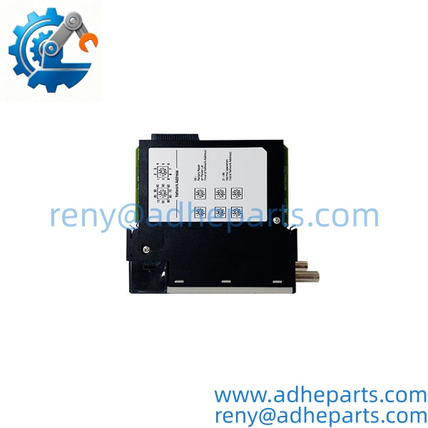
1756-RM/A
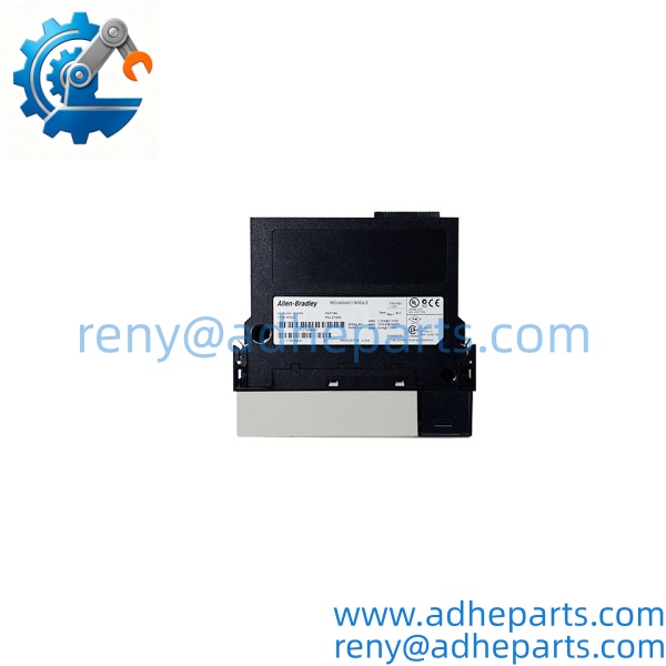
1756-RM/A
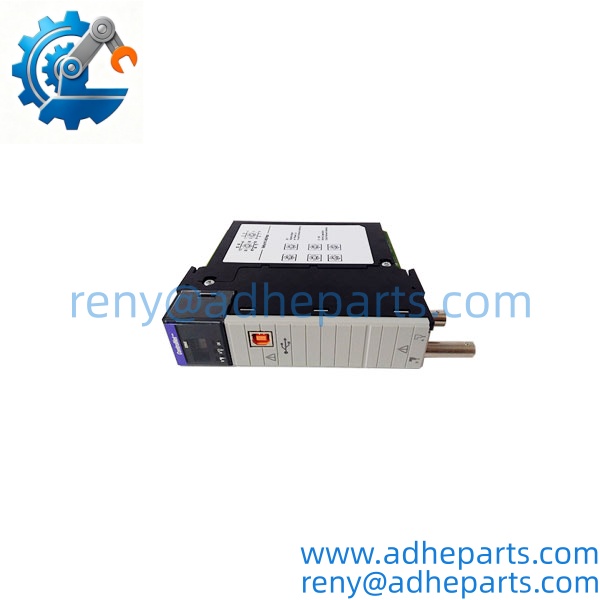
1756-RM/A
QC, Procurement & Logistics SOP
- Inbound Verification
Verify the complete 1756-RM/A catalog number, Series A marking, serial number, hardware revision, status indicators, backplane connector, and dual LC fiber ports. Check for damaged latches, scratched optical connectors, or signs of previous repair. - Live Rig Testing
Install the module in a compatible ControlLogix chassis and verify power-up status, redundancy-module recognition, primary/secondary communication, fiber-link status, and synchronization behavior. Testing should use the appropriate controller, chassis, firmware, and redundancy configuration. - QA & Anti-Static Packaging
Inspect the backplane connector, fiber interfaces, housing, locking clips, and PCB condition. Protect the module in an anti-static bag and use separate optical-port protection with shock-resistant packaging. - Global Logistics & Export Compliance
Confirm the product description and HS classification according to the actual hardware and destination customs requirements. Prepare the commercial invoice, packing list, origin information, and requested warranty or inspection documents. Protect the LC fiber ports during air or sea shipment.
Technical Pitfalls & Integration Warnings
- Firmware Revision Mismatch
Redundant chassis components must use compatible configurations and firmware. For example, a system configured around V3.1 should not automatically be paired with a V2.8 redundancy configuration. Rockwell documentation requires the redundant components to be appropriately matched, including firmware revisions. - DIP Switch / Configuration Errors
Redundancy operation depends on the controller, chassis, communication modules, slot placement, and redundancy configuration. Do not change the existing system configuration simply to accommodate a replacement RM/A. Record the original slot and system configuration before removal. - Fiber and Connector Incompatibility
The 1756-RM/A uses LC single-mode fiber connections. Damaged optical connectors, incorrect fiber type, excessive bend radius, or an incorrectly connected primary/secondary path can prevent synchronization even when the module powers up normally. - ESD Damage During Unboxing
The module contains electronic circuitry and exposed backplane contacts. Use an ESD-safe workstation and keep protective caps on the optical interfaces during handling. Do not touch the backplane connector or optical surfaces unnecessarily.
Frequently Asked Questions (FAQ)
1. What is the Allen-Bradley 1756-RM/A used for?
It is a ControlLogix redundancy module used to establish and maintain communication between redundant controller chassis for enhanced system availability.
2. Is 1756-RM/A still an active product?
The Series A version is listed as discontinued in Rockwell Automation’s compatibility and download resources. This makes exact series and firmware verification important when sourcing a replacement.
3. Which controllers are supported?
Rockwell’s technical data lists the 1756-RM redundancy module with ControlLogix 5560 and 5570 controller families. Compatibility should still be checked against the exact controller revision and redundancy firmware.
4. Can 1756-RM/A be replaced directly by 1756-RM/B?
Do not treat the replacement as a simple catalog-number swap. Rockwell documentation distinguishes the RM/A and RM/B generations and provides specific compatibility requirements. The complete controller, chassis, firmware, and redundancy configuration should be checked before substitution.
5. Can 1756-RM/A be mixed with 1756-RM2 modules?
No. Rockwell documentation states that RM2 modules are not interchangeable with the earlier RM/A, RM/B, or RMXT module families within the same redundancy configuration.
6. Can the 1756-RM/A be hot-swapped?
Do not assume it can be hot-swapped. Rockwell’s installation guidance states that when adding redundancy to an operational ControlLogix system, the process should be shut down before installing the redundancy module.
7. What information should be provided for compatibility confirmation?
Provide the 1756-RM/A nameplate, Series marking, firmware revision, controller model, chassis model, redundancy-module configuration, photographs of the fiber ports, and the existing redundancy cable reference. This allows the replacement to be checked against the complete system rather than the catalog number alone.