Description
Note: Many products are not yet listed. Please contact us for more product information. Our supply channels are constantly expanding, and we currently have 20 stable shared supply channels. Please confirm the model, product, price, and all other necessary information with customer service before placing an order. We offer new, refurbished, and used products, and prices are adjusted according to the year of the item you require.
Key Technical Specifications
| Parameter | Specification |
|---|---|
| Manufacturer | Acquisition Logic / UTEX |
| Model | AL81G |
| Product Type | 1 GHz A/D Digitizer Board |
| Analog Input | 1 channel |
| Sampling Rate | 1 GS/s maximum |
| Resolution | 8 bit |
| Analog Bandwidth | DC to 350 MHz |
| Input Impedance | 50 Ω |
| Input Ranges | 125, 250, 500 mV and 1 V peak-to-peak |
| Onboard Acquisition Memory | 64 MSamples |
| Optional Memory | 256 MB option |
| Host Bus | PCI, 32-bit, 33 MHz |
| PCI Burst Transfer | Up to 133 MB/s |
| Analog Connector | BNC |
| Trigger Connector | BNC |
| Trigger Sources | Signal threshold, encoder, software, external |
| Internal Trigger | 3-pin header |
| DMA | Scatter/gather DMA |
| Board Dimensions | Approx. 9.35 × 4.2 in |
| Power | +5 V, +3.3 V, +12 V, -12 V rails |
The original AL81G specification gives 1 GS/s at 8-bit resolution, sampling rates of 1000, 500, 250, and 100 MSamples/s, 64 MSamples of onboard memory with an optional 256 MB configuration, and a 32-bit/33 MHz PCI interface.
The analog section uses a 50 Ω input and supports 125 mV, 250 mV, 500 mV, and 1 V peak-to-peak input ranges. The board provides BNC connections for analog input and triggering and supports PCI bus-master DMA transfers.
Product Introduction (Anti-Template)
The Acquisition Logic AL81G is built for situations where a conventional low-speed data acquisition card simply cannot capture the waveform detail required. Its single analog input can sample at up to 1 GS/s with 8-bit resolution, while the analog front end provides bandwidth up to 350 MHz. The board also supports threshold, encoder, software, and external triggering for controlled transient acquisition.
This is a measurement and digitization board, not a PLC controller or industrial communication module. It was designed for PCI-based host systems, so the original computer platform, driver environment, acquisition software, and trigger configuration are all part of the compatibility equation.
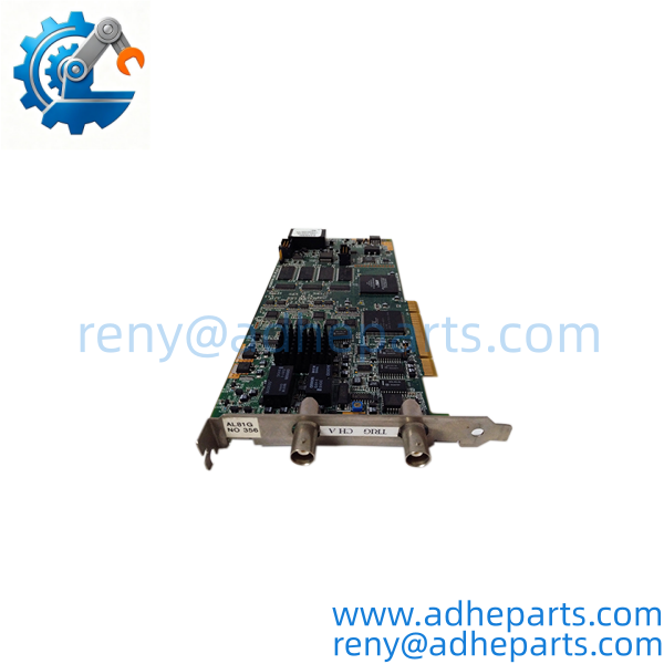
AL81G
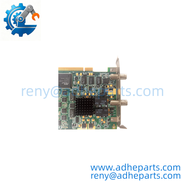
AL81G
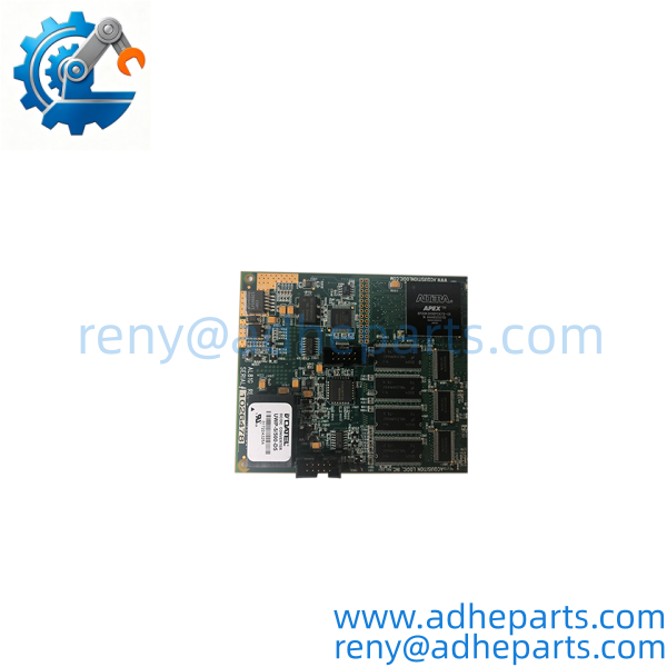
AL81G
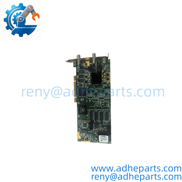
AL81G
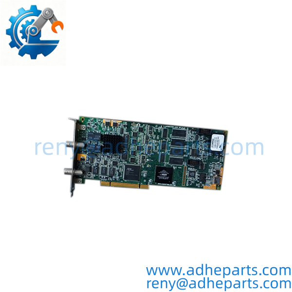
AL81G
QC, Procurement & Logistics SOP
1) Inbound Verification
Verify the board marking as AL81G and inspect the PCI edge connector, BNC connectors, PCB, components, mounting bracket, and revision markings. Record the serial number and visible board configuration before testing.
2) PCI Host Testing
Install the card in a compatible PCI test workstation and verify that the host system recognizes the board correctly. Because the AL81G uses a 32-bit, 33 MHz PCI interface, a modern computer with a physically similar slot should not automatically be considered compatible.
3) Signal Acquisition Test
Use a calibrated signal source within the specified input range and verify representative acquisition at the applicable sampling rates. Check waveform capture, amplitude response, trigger behavior, and DMA data transfer.
4) Trigger Verification
Test at least one threshold-trigger function and, where the customer’s application requires it, verify encoder, software, or external trigger operation. The trigger configuration is particularly important in automated inspection systems.
5) Memory & Data Transfer Check
Verify onboard acquisition memory operation and host-side data transfer. The original specification identifies 64 MSamples of acquisition memory and PCI burst transfer rates up to 133 MB/s.
6) Driver & Software Verification
Before shipment, confirm the customer’s operating system, Acquisition Logic/UTEX driver, acquisition software, and existing system configuration. Original support documentation lists drivers for software environments including Winspect and InspectionWare.
7) QA & ESD Packaging
Handle the board using ESD-safe procedures. Place it in an anti-static bag and protect the PCI edge connector and BNC connectors with rigid cushioning. Avoid pressure on the front-panel connectors.
8) Global Logistics & Export Compliance
Confirm the commercial invoice description, country of origin, HS classification, declared value, and destination import requirements. Describe the product according to its actual function as a high-speed A/D digitizer/data acquisition board.
9) Secure Air/Sea Packaging
Use an anti-static inner package, moisture protection, rigid foam cushioning, and a strong outer carton. The board should be immobilized so that the PCI connector and BNC connectors cannot move against the packaging during transportation.
Technical Pitfalls & Integration Warnings
1) The AL81G is not a PLC I/O module.
It is a high-speed measurement/digitizer board. Its job is to convert a high-frequency analog waveform into digital acquisition data for a host computer.
2) Do not confuse 1 GS/s with analog bandwidth.
The maximum sampling rate is 1 GS/s, while the specified analog bandwidth is DC to 350 MHz. These are different specifications and should not be presented as the same thing.
3) PCI compatibility is a major replacement issue.
The uses a 32-bit, 33 MHz PCI bus and supports bus-master DMA. A PCIe-only workstation is not a drop-in host platform for this card.
4) Input impedance and signal range must be checked.
The original specification identifies a 50 Ω input and input ranges of 125 mV, 250 mV, 500 mV, and 1 V peak-to-peak. Connecting a signal outside the intended range can produce invalid acquisition results or damage the front end.
5) Trigger configuration can be application-specific.
The supports threshold, encoder, software, and external triggering. A replacement card should therefore be tested using the same trigger architecture as the customer’s existing system rather than only checking whether analog samples can be collected.
6) The product is obsolete.
The original manufacturer specification states that the became obsolete in August 2013 and points to the AL81xGTe family as the modern replacement. A newer replacement is not necessarily a mechanical or software drop-in, so legacy systems may specifically require the original .
Frequently Asked Questions (FAQ)
Q1: What is the Acquisition Logic ?
It is a single-channel, high-speed A/D digitizer board designed for rapid analog waveform acquisition.
Q2: What is the maximum sampling rate of the ?
The maximum specified sampling rate is 1 GS/s, with 8-bit resolution.
Q3: How many analog input channels does the have?
The has one analog input channel.
Q4: What is the ‘s analog bandwidth?
The original specification gives an analog bandwidth of DC to 350 MHz.
Q5: What type of computer interface does the use?
It uses a 32-bit, 33 MHz PCI interface and supports PCI bus-master DMA transfers.
Q6: Is the still manufactured?
The original manufacturer documentation states that the product was obsolete as of August 2013 and identifies the AL81xGTe family as the modern replacement path.
Q7: What should I provide when requesting an replacement?
Provide a photo of the existing , board revision, host computer model and PCI configuration, operating system, acquisition software/driver version, input signal type, and trigger method. For a legacy test or inspection system, these details can be more important than the model number alone.