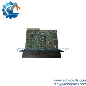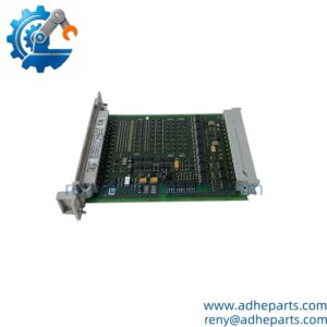
Description
Note: Many products are not yet listed. Please contact us for more product information. Our supply channels are constantly expanding, and we currently have 20 stable shared supply channels. Please confirm the model, product, price, and all other necessary information with customer service before placing an order. We offer new, refurbished, and used products, and prices are adjusted according to the year of the item you require.
Key Technical Specifications
| Parameter | Value |
|---|---|
| Product Type | Analog Input Module |
| Manufacturer | ABB |
| Model in ABB Catalog | 07 EA 90-S |
| Order Code | GJR 525 1200 R 0101 |
| Analog Input Channels | 4 |
| Input Signal | 4–20 mA |
| Resolution | 12-bit |
| Power Supply | 24 VDC |
| Bus Interface | CS31 bus |
| Electrical Isolation | Isolated from the CS31 bus |
| Compatible System | ABB Procontic T200-S / Advant Controller 31-S |
| Required Bus Coupler | 07 CS 61 |
| Compatible Central Units | 07 ZE 61, 07 ZE 62, 07 ZE 63 |
| Compatible Engineering Software | 907 PC 336 |
| Approximate Weight | 0.47 kg |
The ABB catalog specifies four 4–20 mA analog inputs with 12-bit resolution. It also states that this module requires the specified central units and 07 CS 61 bus coupler. Do not assume compatibility with every AC31 or CS31 configuration.
ms.nordwel.com+1
Product Introduction
The ABB 07 EA 90-S is a four-channel analog input module designed for ABB Procontic T200-S and compatible Advant Controller 31-S architectures. It receives 4–20 mA signals from field transmitters and converts them into digital values for process monitoring and control.
With 12-bit resolution, a 24 VDC supply, and electrical isolation from the CS31 bus, the module provides an interface between field instrumentation and the controller. Its system compatibility is configuration-specific, making verification of the bus coupler and central unit essential before replacement.
ms.nordwel.com+1
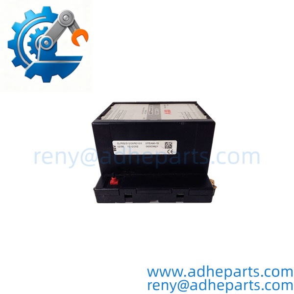
07EA90-SI
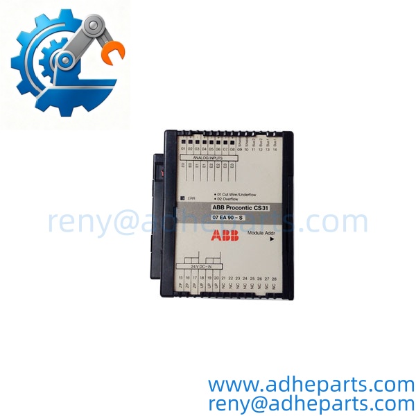
07EA90-SI
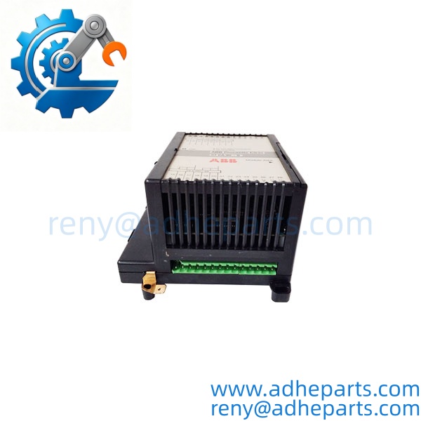
07EA90-SI
Application Scenarios & Field Experience
In process automation, a failed analog input channel can interrupt the measurement of a critical variable such as pressure, flow, or temperature. Replacing the module requires more than matching the physical dimensions. Engineers must verify the 4–20 mA signal wiring, channel assignment, controller compatibility, and CS31 bus configuration. An incorrect module selection can leave the field transmitter connected but prevent the controller from receiving valid process data.
Typical application scenarios
- Chemical Processing — Receives 4–20 mA pressure or flow transmitter signals for monitoring process conditions.
- Water Treatment — Collects flow, pressure, and level transmitter signals for pump and treatment process monitoring.
- Power Generation — Interfaces compatible instrumentation signals with legacy ABB control systems for auxiliary process monitoring.
- Industrial Manufacturing — Acquires analog measurements from production equipment and process instrumentation for controller-based monitoring.
Illustrative engineering scenario, not a documented customer installation: A plant experiences an abnormal reading on one analog measurement channel. The maintenance engineer checks the transmitter output, loop wiring, and supply before identifying a possible module fault. A replacement 07 EA 90-S is checked against the original order code and system configuration. After installation, the engineer verifies each 4–20 mA channel against a known input value before returning the measurement loop to service.
Standard Operating Procedure (SOP) for Quality Control
1. Visual & Origin Inspection
- Verify the ABB product label, model designation, and order code.
- Inspect the PCB, housing, terminal connections, and bus connector for physical damage or corrosion.
- Check available OEM packaging, serial number information, and origin documentation.
- Confirm whether the unit is marked 07 EA 90-S or 07 EA 90-SI.
2. Functional Testing
- Where a compatible test setup is available, verify operation with the specified 24 VDC supply.
- Check module startup and diagnostic indications.
- Apply suitable 4–20 mA test signals to the input channels.
- Verify that the corresponding digital readings are received by the compatible controller.
- Record the channels tested and any limitations of the test setup.
3. Firmware & Configuration Verification
- This is an analog I/O module; independent firmware verification may not apply.
- Confirm the compatible central unit, 07 CS 61 bus coupler, and 907 PC 336 engineering environment.
- Check channel assignments, transmitter ranges, and controller-side scaling.
- Confirm that the replacement order code matches the installed system requirements.
4. ESD-Safe Packaging
- Handle the module with appropriate electrostatic-discharge precautions.
- Protect exposed electronic components and connectors with anti-static packaging.
- Use protective cushioning to prevent impact damage during transportation.
5. Pre-Shipment Documentation
- Provide actual product photos and a clear label photo.
- Confirm the model designation and order code.
- Provide available inspection records and report only tests completed on the specific unit.
Frequently Asked Questions (FAQ)
Q1: Can the ABB 07 EA 90-SI replace other ABB analog input modules?
A: Not automatically. The 07 EA 90-S has four 4–20 mA input channels and 12-bit resolution. Other ABB modules may have different channel counts, signal ranges, or system requirements. Compare the complete order code and electrical specifications before replacement.
Q2: What warranty is available?
A: We offer a 12-month warranty, subject to confirmed order terms. The product condition and warranty coverage will be stated in the order confirmation.
Q3: Is the 07 EA 90-SI available for immediate shipment?
A: Stock availability and condition must be confirmed before ordering. For confirmed available stock, our usual arrangement is shipment within one week after payment. Product photos and live video inspection can be arranged before shipment.
Q4: Does firmware compatibility matter for this module?
A: The module is primarily an analog I/O device rather than an independently programmable controller. The more important checks are compatibility with the central unit, CS31 bus coupler, engineering environment, and controller configuration.
Q5: What should engineers check before installing the replacement?
A: Confirm the exact order code, 24 VDC supply, 4–20 mA signal wiring, and channel assignments. Also verify that the installation uses a compatible 07 CS 61 bus coupler and central unit. Follow the approved shutdown and electrical isolation procedures before disconnecting field wiring.