Description
Note: Many products are not yet listed. Please contact us for more product information. Our supply channels are constantly expanding, and we currently have 20 stable shared supply channels. Please confirm the model, product, price, and all other necessary information with customer service before placing an order. We offer new, refurbished, and used products, and prices are adjusted according to the year of the item you require.
Key Technical Specifications
Do not order against this table alone. I cannot confirm the part type from the number. Match every line against the OEM datasheet for your specific application.
| Parameter | Value |
|---|---|
| Model | 200-566-000-012 |
| Brand | Vibro-Meter |
| Part Type | Verify — confirm whether this is a sensor, cable, card, or module |
| Compatible System | Verify — VM600 rack or standalone |
| Compatible Machine / Application | Verify — sensor and cable selections are machine-specific |
| Measurement Range | Verify with OEM datasheet |
| Sensitivity | Verify with OEM datasheet |
| Frequency Response | Verify with OEM datasheet |
| Connector Type | Verify — connector arrangement varies by part type |
| Cable Length | Verify — if this is a cable assembly |
| Mounting | Verify — depends on the part type and machine interface |
| Operating Temperature | Verify — machine surface temperatures affect the rating |
| Weight | Verify with OEM datasheet |
| Certifications | Verify on the specific unit’s label — hazardous area ratings may apply |
Product Introduction
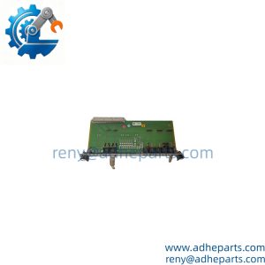
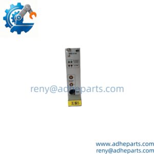
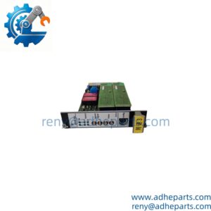
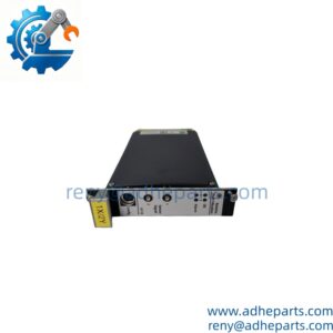
The Vibro-Meter 200-566-000-012 is a component from the VM600 machinery protection system. Vibro-Meter built the VM600 platform for turbine, compressor, and pump monitoring, and the 200-566 prefix covers parts in that family — transducers, cables, interface cards, and rack modules. I cannot tell you from the number alone whether this is a proximity probe, an accelerometer, a cable assembly, or a card that plugs into a VM600 rack. I am not going to guess.
Here is what I can tell you as a straight answer: on Vibro-Meter hardware, compatibility is system-specific and often channel-specific. A sensor that works on one machine may not work on another because the sensitivity, the connector type, and the cable length must all match the input card. A card that fits one VM600 rack may not initialize in another if the firmware revision is different. Before you order, read the label on the existing part and cross-reference it against the OEM datasheet for your system. If you send me a photo of the part and the rack it came out of, I will confirm what you are looking at.
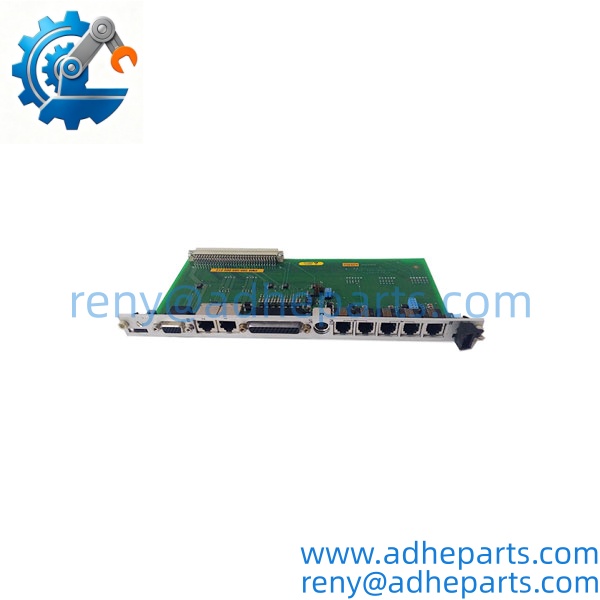
200-566-000-012
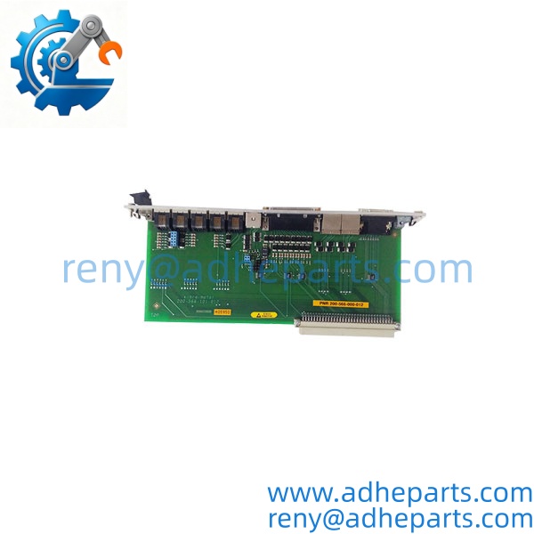
200-566-000-012
Application Scenarios & Field Experience
Part 1 – Narrative Paragraph
The failure that costs the most on a machinery protection system is a mismatched component that passes a bench check and still gives bad data. I have seen a plant replace a vibration sensor with a different sensitivity and then chase a “sensor fault” for two weeks. The sensor was fine. The system was reading the wrong scale factor because the input card was configured for a different transducer. On Vibro-Meter hardware, the sensor, the cable, and the input card form a matched set. Change one and you change the calibration. That is the rule that matters more than any single specification on the datasheet.
Part 2 – Numbered List (Application Scenarios)
- Power Generation – Steam Turbine Monitoring – Proximity probes and accelerometers measure shaft vibration, axial displacement, and bearing condition. The sensor and cable must match the input card’s calibration, or the protection system will trip on false data.
- Oil & Gas – Centrifugal Compressor Protection – Accelerometers on compressor bearings detect early-stage wear. The transducer must match the rack module’s input type and sensitivity.
- Petrochemical – Reciprocating Compressor Monitoring – Probes and cables monitor rod drop and crosshead vibration. The cable length and connector type are application-specific, and a mismatch introduces noise into the signal.
- Hydroelectric – Hydro Turbine Bearing Monitoring – Proximity probes measure shaft orbit and bearing clearance. The wide temperature rating and sealed connectors handle the humid powerhouse environment.
Part 3 – Short Field Story
A gas plant had a compressor that would trip on “high radial vibration” every few weeks. The crew had replaced the probe and the extension cable and the fault kept returning. We asked for the input card part number before shipping anything. It turned out the replacement probe had a different sensitivity than the original, and the card was still configured for the old transducer. The system was reading a scaled signal that looked like a real vibration event. Once the correct sensor and cable set was installed and the card verified, the trips stopped. The hardware had been fine — the calibration was wrong.
Standard Operating Procedure (SOP) for Quality Control
- Visual & Origin Inspection – We verify the Vibro-Meter marking, the 200-566-000-012 part number, and the date code. We inspect connectors, cable jackets, and sensor bodies for damage. A part with a damaged connector or a cracked housing is rejected.
- Part Number and Revision Documentation – We read and photograph the full part number, the revision suffix, and any serial number or date code. That record ships with the part so you can compare it against the unit you are replacing.
- Compatibility Cross-Check – We verify the part number against the OEM documentation for the system and machine you specify. A part that does not match the requested application is set aside rather than shipped.
- Electrical Verification – For sensors and cables, we measure the DC resistance and check for shorts or opens. For cards and modules, we power the unit on a bench fixture and verify the output against a reference signal.
- Mechanical Fit Verification – For probes and mounting hardware, we verify the thread type, tip diameter, and case dimensions against the OEM specification.
- Functional Test (where applicable) – For rack modules and cards, we run a functional test on a bench fixture and confirm the unit reports correctly.
- ESD-Safe Packaging – Electronic components are wrapped in anti-static film. Probes and cables are coiled to the specified bend radius and secured. All parts are packed with the connectors protected and shipped in a double-wall carton with handling labels.
Frequently Asked Questions (FAQ)
Q1: What part type is 200-566-000-012?
A: I cannot confirm the part type from the number alone. Vibro-Meter uses the 200-566 prefix across sensors, cables, cards, and rack modules, and the number does not tell me which. Send us a photo of the part label and the rack or machine it came out of, and we will confirm it against the OEM documentation before you order.
Q2: Is this part compatible with all Vibro-Meter systems?
A: No. Vibro-Meter hardware is system-specific and often channel-specific. A sensor and cable set that works on one machine may not work on another because the sensitivity, connector type, and cable length must all match the input card. Confirm compatibility against your system’s documentation before ordering.
Q3: What is the warranty on this part?
A: We offer a 12-month warranty from the ship date. It covers manufacturing defects under normal operating conditions. It does not cover damage from incorrect installation, mechanical impact, or operation beyond the rated range. For electrical components, the warranty is void if the part shows evidence of overvoltage or reversed polarity. Every part ships with a test report where applicable.
Q4: Do you actually have this in stock?
A: Vibro-Meter inventory moves quickly, and stock varies by part number and revision. Confirm availability before you plan an outage. If we are out, we will tell you what we actually have rather than quote a date we cannot hold.
Q5: Any installation pitfalls I should watch for?
A: Four. First, on sensor systems, the sensor, cable, and input card form a matched set — changing one changes the calibration. Verify the sensitivity and cable length before you install. Second, route sensor cables away from high-voltage wiring and secure them at the original clamp points; a cable that rubs will fail in weeks. Third, on rack modules, verify the firmware revision matches the rack before you insert the module. Fourth, after the swap, verify the reading with a known reference before you return the protection system to service. A part that powers up is not necessarily giving correct data.