Description
Note: Many products are not yet listed. Please contact us for more product information. Our supply channels are constantly expanding, and we currently have 20 stable shared supply channels. Please confirm the model, product, price, and all other necessary information with customer service before placing an order. We offer new, refurbished, and used products, and prices are adjusted according to the year of the item you require.
3. Key Technical Specifications
Confirm each line against the OEM datasheet and the label on your existing module before ordering. Channel configuration, sensor type, and terminal block part numbers must be verified for your specific build.
| Parameter | Value |
|---|---|
| Model | A6110 |
| Brand | Emerson (CSI) |
| Product Family | CSI 6500 Machinery Health Monitor |
| Module Type | Vibration monitoring module |
| Input Channels | 2 (individually configurable) |
| Input Signal Types | Proximity probe (eddy current), velocity transducer, accelerometer — verify supported types on your build |
| Input Voltage Range | Verify with OEM datasheet |
| Frequency Response | Verify with OEM datasheet — confirm low and high cutoff per sensor type |
| A/D Resolution | Verify with OEM datasheet |
| Measurement Parameters | Overall vibration, gap voltage, 1X amplitude and phase, 2X, nX — verify firmware capability |
| Alarm and Trip Setpoints | Configurable per channel — verify count and voting options |
| Relay Outputs | Verify — alarm and trip contacts may route through the rack backplane |
| Isolation | Field side to logic side — verify isolation voltage |
| Backplane Interface | CSI 6500 rack backplane — verify slot assignment and chassis compatibility |
| Terminal Block | External terminal block required — verify the correct part number for your module and rack |
| Configuration Software | CSI 6500 configuration tool — verify supported version |
| Status Indicators | Module OK and per-channel status LEDs — verify arrangement |
| Operating Temperature | 0 °C to +60 °C (typical — verify) |
| Storage Temperature | –40 °C to +85 °C (typical — verify) |
| Humidity | 5% – 95% RH, non-condensing |
| Weight | Verify with OEM datasheet |
| Certifications | CE, UL, CSA, API 670 compliant when configured in a compliant rack — verify on the unit label |
4. Product Introduction
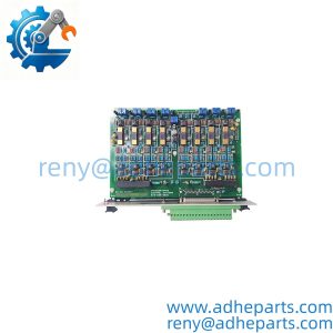
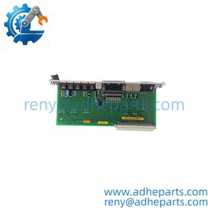
The Emerson A6110 is a two-channel vibration monitoring module for the CSI 6500 Machinery Health Monitor. It accepts signals from proximity probes, velocity transducers, or accelerometers and converts them into vibration measurements — overall amplitude, gap voltage, and harmonic components — for protection and trending on turbines, compressors, and large rotating machinery.
The engineering value is the per-channel configurability. Each of the two channels can be set for a different sensor type and a different measurement parameter, so one module can monitor a proximity probe on a turbine bearing and an accelerometer on the same machine’s gearbox. In my experience, that flexibility reduces the spare parts inventory a plant has to carry — one card covers multiple measurement points instead of a separate card for each sensor type.
Two things decide whether a swap works. First, the terminal block. The A6110 does not land field wiring directly — it mates with an external terminal block that carries the marshalling. Second, the configuration. The sensor type, the scale factor, and the alarm setpoints live in the rack configuration, not in the module. Verify the configuration file is current and backed up before you swap the card.
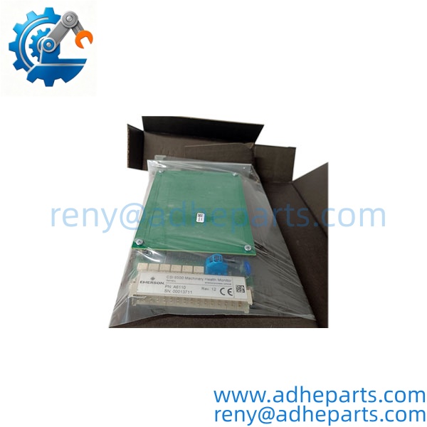
A6110
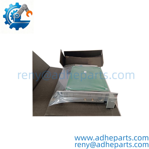
A6110
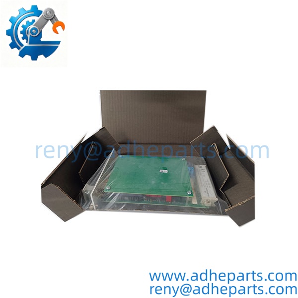
A6110
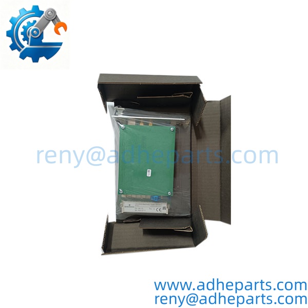
A6110
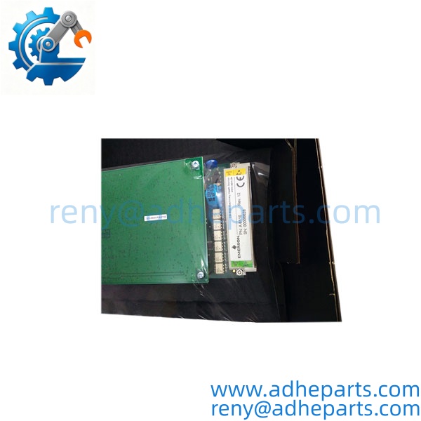
A6110
5. Application Scenarios & Field Experience
Part 1 – Narrative Paragraph
The failure that hurts most on a vibration monitoring module is not a dead channel — it is a channel that reads normal while the machine is degrading. The module still communicates, the alarm setpoints still evaluate, and the trend shows a flat line. I have seen that on a compressor where the proximity probe had lost its gap voltage reference and the module was reading a frozen value that looked like steady operation. The machine was actually developing a bearing fault, and the protection did not catch it. When you replace an A6110, verify the gap voltage and the sensor response on each channel against a known reference before you return the machine to service. A module that powers up is not necessarily measuring correctly.
Part 2 – Numbered List (Application Scenarios)
- Power Generation – Steam Turbine Bearing Monitoring – The module reads proximity probes on turbine bearings for shaft vibration and axial position. The configurable setpoints drive the alarm and trip relays, and the harmonic data feeds the plant’s predictive maintenance program.
- Oil & Gas – Centrifugal Compressor Protection – Used to monitor radial vibration and thrust position on compressors. The 2-channel design covers one bearing pair per module, and the isolated inputs prevent ground loops between the machine and the rack.
- Petrochemical – Reciprocating Compressor Monitoring – The module reads velocity transducers and accelerometers on compressor frames and cylinders. The per-channel configuration allows one module to cover both the frame and the cylinder.
- Hydroelectric – Hydro Turbine Vibration – Used to measure shaft vibration and eccentricity on hydro units. The wide frequency response captures both the low-speed fundamental and the higher-frequency components that indicate cavitation.
Part 3 – Short Field Story
A gas plant had a centrifugal compressor that developed a bearing failure that the vibration system did not catch. The post-mortem showed the proximity probe channel had been reading a frozen value for weeks. The module reported no fault, the alarm never triggered, and the trend looked normal. When the plant replaced the A6110 module and re-verified the gap voltage on the new channel, the reading jumped to a healthy value — the old module’s front-end had failed in a way that produced a steady output rather than a fault. The plant now verifies gap voltage on every channel after a module replacement. That check takes two minutes and catches the failure mode that a self-test does not.
6. Standard Operating Procedure (SOP) for Quality Control
- Visual & Origin Inspection – We verify the Emerson/CSI marking, the A6110 model string, and the date code. We inspect the backplane connector for bent pins and the module housing for cracks or moisture ingress. A module with a damaged connector or evidence of rework is rejected.
- Revision and Configuration Documentation – We read and photograph the full model string, the firmware revision, and the module revision letter. We extract and archive any existing configuration before shipping. That record ships with the module so you can compare it against the unit you are replacing.
- Chassis Fit Verification – Each module is seated in a CSI 6500 test rack to confirm the connector engages fully and the retention mechanism holds. A module that fits loosely will cause intermittent backplane faults in the field.
- Power-Up and Self-Test – The module is powered in a live rack and we verify it completes its boot sequence and that the rack controller recognizes the module type without a fault.
- Input Channel Verification – We inject calibrated vibration signals into each channel for each supported sensor type — proximity probe, velocity, and accelerometer. We verify the module’s reported overall amplitude and gap voltage against the reference. Accuracy must stay within the OEM specification.
- Alarm and Trip Verification – We drive each channel above and below its configured setpoints and verify the module reports the correct alarm and trip state to the rack controller.
- Diagnostic Function Test – We simulate an open sensor and a shorted sensor and verify the module reports the fault. A module that measures correctly but does not report faults is not acceptable for machinery protection.
- ESD-Safe Packaging – The module is wrapped in anti-static film, seated in a conductive foam insert with the connectors protected by rigid shrouds, and packed in a double-wall carton with static warning labels.
7. Frequently Asked Questions (FAQ)
Q1: Does the include the terminal block?
A: No. The is the module only. Field wiring lands on an external terminal block that mates with the module through the rack. The terminal block is a separate part number, and you must verify it matches your module type and chassis. If you send us the terminal block part number and the rack model, we can confirm the match before you order.
Q2: Can I mix sensor types on the two channels?
A: Yes. Each channel is independently configurable, so you can run a proximity probe on one channel and an accelerometer on the other. The configuration is set in the rack software, not on the module itself. Verify the supported sensor types against the OEM datasheet for your firmware revision before you order.
Q3: What is the warranty on this module?
A: We offer a 12-month warranty from the ship date. It covers input channel failure, backplane connector failure, and diagnostic circuit failure under normal operating conditions. It does not cover damage from hot-swapping the module outside the OEM procedure, bent pins from forced insertion, or field wiring faults that cause a channel to fail. We test every module in a live CSI 6500 rack across all supported sensor types before it ships.
Q4: Do you have this in stock?
A: Emerson CSI 6500 inventory moves quickly, and stock varies by revision. Confirm availability before you plan an outage. If we are out of the revision you need, we will tell you what we actually have rather than quote a date we cannot hold.
Q5: Any installation pitfalls I should watch for?
A: Four. First, verify the terminal block part number matches the module and the rack before you install. Second, record the channel configuration and the sensor scale factors from the old module’s setup before you remove it — these live in the rack, but confirming them prevents a configuration error. Third, check the field wiring and the sensor cables for damage or shielding problems before you install the replacement. Fourth, after the swap, verify the gap voltage and the vibration reading on each channel against a known reference before you return the machine to service. A module that powers up is not necessarily measuring correctly.