Description
Note: Many products are not yet listed. Please contact us for more product information. Our supply channels are constantly expanding, and we currently have 20 stable shared supply channels. Please confirm the model, product, price, and all other necessary information with customer service before placing an order. We offer new, refurbished, and used products, and prices are adjusted according to the year of the item you require.
Key Technical Specifications
| Parameter | Specification |
|---|---|
| Manufacturer | General Electric |
| Model | DS200DCFBG1BJB |
| Functional Acronym | DCFB |
| Board Type | Power Supply Board |
| Product Family | DS200 |
| Associated Systems | Mark V / AC2000 / DC2000 / related drive applications |
| Input Power | 38 VAC and 115 VAC; 24 VDC in applicable configurations |
| Main DC Outputs | +5 VDC, +15 VDC, -15 VDC, +24 VDC, -24 VDC |
| +24 VDC Rating | 3 A |
| -24 VDC Rating | 1 A |
| +15 VDC Outputs | 0.8 A each |
| +5 VDC Output | 4 A |
| Protective Devices | FU1, FU2, FU3 |
| DIP Switches | 7 configurable switch blocks |
| Jumpers | 12 configurable jumpers |
| Test Points | 5 |
| Board Connectors | 18 plug connectors plus 9 stab connectors |
| Manual Reference | GEI-100028C |
The original GEI-100028C manual specifies the DCFB power-supply outputs and identifies the board as applicable to DC2000, CB2000, EX2000, FC2000, GF2000, ME2000, and AC2000 IGBT drive applications.
Product Introduction (Anti-Template)
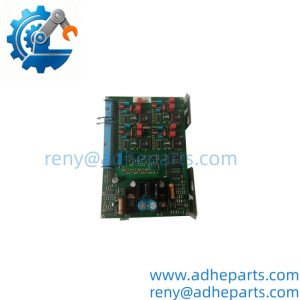
The GE DS200DCFBG1BJB is a DCFB Power Supply Board designed for GE industrial drive and control equipment. Its primary job is not simply to distribute incoming power: it generates several regulated control-level supplies used by the drive electronics and also contains circuits associated with motor voltage/current feedback, AC line monitoring, and motor-field functions.
The board is found in legacy GE drive platforms including DC2000, CB2000, EX2000, FC2000, GF2000, ME2000, and AC2000 applications. The exact jumper and DIP-switch arrangement depends on the host application, so the complete board number and existing configuration should be checked before replacement. (This is one of those GE boards where copying settings from a visually similar card can cause trouble.)
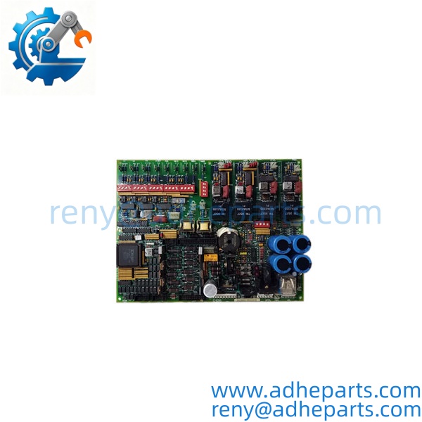
DS200DCFBG1BJB
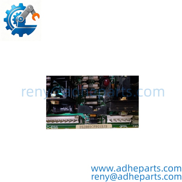
DS200DCFBG1BJB
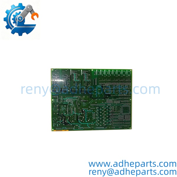
QC, Procurement & Logistics SOP
1) Inbound Identification
Verify the complete nameplate and board markings before testing:
- DS200DCFBG1BJB
- DCFB
- Hardware/revision markings
- Artwork revision
- Connector and PCB condition
Do not purchase solely against the shorter DS200DCFBG1B designation when the installed system requires the complete DS200DCFBG1BJB configuration.
The DCFB manual covers both DS200DCFBG1A and DS200DCFBG1B variants, so revision control matters when matching an engineering spare.
2) Power-Supply Verification
A suitable test setup should verify the applicable power-input arrangement and regulated outputs.
Where supported by the test configuration, check:
- +5 VDC
- +15 VDC
- -15 VDC
- +24 VDC
- -24 VDC
- Fuse status
- Test-point readings
- Output stability under appropriate load
Do not apply arbitrary external voltage simply because the board has a visible power connector. The correct input arrangement depends on the host drive application and wiring.
3) Feedback and Monitoring Verification
The DCFB board also handles several signals that interface with the drive control electronics. GE documentation describes circuits for motor voltage, armature current, motor-field current in applicable applications, and AC line current/voltage monitoring.
Where the customer’s application permits, verify the relevant feedback path and connector continuity rather than treating the board as an isolated power supply.
4) Jumper & DIP-Switch Verification
The board contains configurable jumpers and seven DIP-switch blocks. Some settings affect scaling and signal-conditioning circuits. For example, GE documentation specifies switch settings associated with AC line current-transformer burden selection and voltage-feedback scaling.
Record the original configuration before removing a replacement card. Photographing the installed board is strongly recommended.
5) ESD and Physical Inspection
Inspect:
- PCB surface
- Plug connectors
- Stab connectors
- Fuses
- LEDs and neon indicator
- Capacitors
- Resistors and power components
- Solder joints
- Signs of overheating or contamination
Package the board in an antistatic bag with impact protection. For export shipments, use moisture-resistant and vibration-resistant packaging.
6) Export & Logistics
For international orders, the commercial invoice and packing list should identify the item as an industrial drive power supply/control board and include the exact GE part number.
HS classification should be confirmed against the actual product and the destination customs requirements rather than relying on a generic HS number copied from another GE board.
For urgent maintenance orders, confirm actual stock condition, inspection time, and dispatch schedule before quoting a fixed delivery date.
Suitable Incoterms can include EXW, FCA, or DAP, depending on the buyer’s freight and customs arrangement. Import duty, VAT, brokerage, and destination clearance remain subject to local regulations.
Technical Pitfalls & Integration Warnings
1) Do Not Treat It as a Generic DC Power Supply
The DCFB board combines power-supply functions with drive-specific feedback and control circuits. Replacing it with a generic power module will not reproduce the required signal-conditioning and interface functions.
2) Input Voltage Must Match the Application
GE documentation identifies 38 VAC and 115 VAC inputs from the control power transformer, with 24 VDC applicable to certain configurations. Do not assume every DCFB installation uses the same input arrangement.
3) DIP Switches and Jumpers Are Application-Specific
There are 12 configurable jumpers and seven DIP-switch blocks. Several are involved in feedback scaling, VCO circuits, and application-specific signal conditioning. Incorrect settings can produce apparently incorrect feedback even when the board powers up normally.
4) Do Not Ignore the Companion Control Board
The DCFB interfaces with other drive-control electronics such as the SDCC/LDCC. A failed feedback signal or missing control voltage is not automatically proof that the DCFB itself is defective. Check wiring, fuses, downstream loading, connector condition, and the companion board before replacing multiple cards.
5) Revision Matching Matters
DS200DCFBG1BJB contains more detailed revision information than the basic DS200DCFBG1B family designation. If the customer’s original board has a specific hardware or artwork revision, provide the complete part number and board photos for compatibility verification.
6) High-Voltage Maintenance Hazard
This board can be installed in drive equipment containing hazardous AC and DC voltages. GE’s manual specifically warns that installation and maintenance should only be performed by adequately trained personnel familiar with the equipment and instructions.
Frequently Asked Questions (FAQ)
Q1. What is the GE DS200DCFBG1BJB used for?
It is a DCFB Power Supply Board used in several GE industrial drive and control platforms. It generates control-level DC power and also handles selected voltage, current, and drive-monitoring circuits.
No. It is a drive/control power supply board with application-specific feedback and interface circuitry, not a general-purpose PLC digital or analog I/O module.
Q3. What systems use the DCFB board?
GE documentation lists DC2000, CB2000, EX2000, FC2000, GF2000, ME2000, and AC2000 IGBT drive applications. The EX2000 uses the board differently from the drive applications, so the host system should always be confirmed.
Q4. What DC voltages does the DCFB board generate?
The board generates +5 VDC, ±15 VDC, and ±24 VDC control-level supplies. GE’s documentation specifies 3 A for +24 VDC, 1 A for -24 VDC, 0.8 A for each +15 VDC output, and 4 A for the +5 VDC output.
Q5. Can I replace with any DS200DCFB board?
Not automatically. The host application, revision, jumper settings, DIP-switch configuration, wiring, and required feedback circuits must be checked before substitution.
Q6. What should I send when requesting a replacement quote?
Provide the complete part number , a clear photo of the board nameplate, the existing revision markings, and the GE drive/control-system model. A photo of the installed jumper and DIP-switch positions is also useful for compatibility checking.
Q7. How should a surplus DCFB board be tested before shipment?
At minimum, identification, physical condition, connector integrity, fuse condition, regulated power outputs, and relevant feedback/interface circuits should be checked where the appropriate test equipment is available. For an engineering spare, a live inspection video can be supplied before shipment when requested.