Description
Note: Many products are not yet listed. Please contact us for more product information. Our supply channels are constantly expanding, and we currently have 20 stable shared supply channels. Please confirm the model, product, price, and all other necessary information with customer service before placing an order. We offer new, refurbished, and used products, and prices are adjusted according to the year of the item you require.
Product Introduction (Anti-Template)
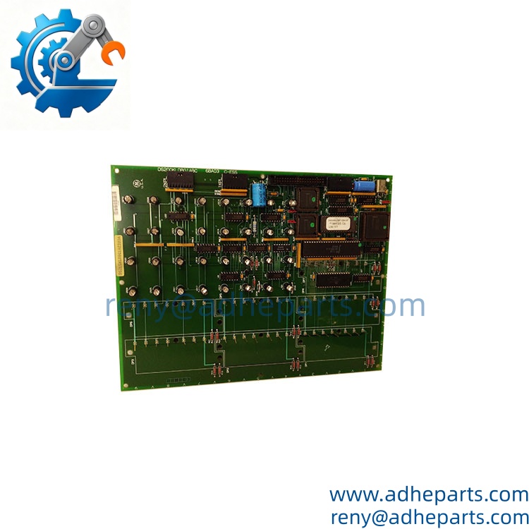
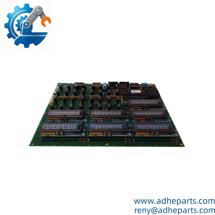
When a legacy turbine cabinet loses its local display or operator indications, troubleshooting becomes unnecessarily difficult even when the underlying controller is still running. The GE DS200KLDBG1ABC is a KLDBG1 display board associated with the Mark V Speedtronic turbine control system. Current spare-parts references identify DS215KLDBG1AZZ03A as a replacement assembly for the DS200KLDBG1ABC.
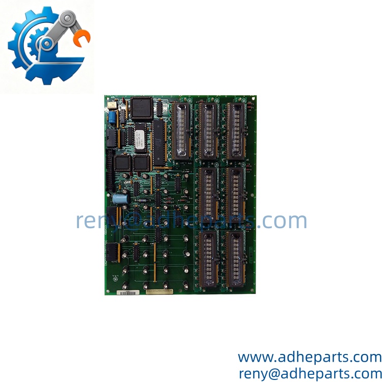
The board provides local visual indication and operator-interface functions rather than acting as the main turbine processor. Published technical references describe a 24 VDC supply, function keys, LED display elements, status indicators, and RS-485 inter-board communication.
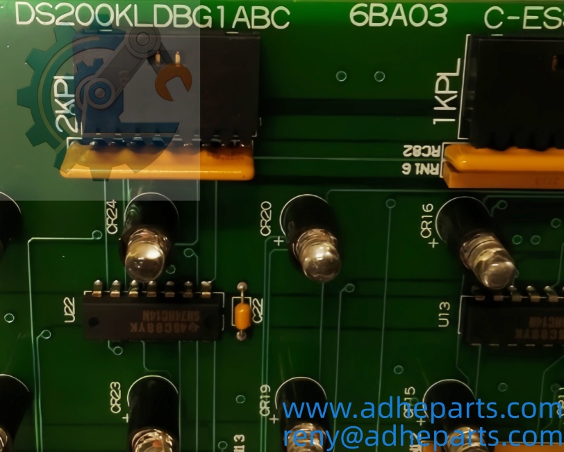
DS200KLDBG1ABC-DS215KLDBG1AZZ03A-label
Key Technical Specifications
| Parameter | Value |
|---|---|
| Manufacturer | General Electric (GE) |
| Legacy Model | DS200KLDBG1ABC |
| Replacement Assembly | DS215KLDBG1AZZ03A |
| Board Designation | KLDBG1 |
| Product Type | Display / Operator Interface Board |
| Control System | GE Mark V Speedtronic |
| Application | Gas and Steam Turbine Control |
| Supply Voltage | 24 VDC |
| Power Consumption | Approx. 2 W |
| Operator Controls | 8 function buttons |
| Display | 7 sets of 16-segment LED digital displays |
| Status Indicators | 32 LED indicators |
| Board Communication | RS-485 |
| Operating Temperature | Approx. 0–60°C |
| Installation | Mark V turbine control cabinet |
| HS Code | 85389099 |
The DS200KLDBG1ABC is specifically identified in spare-parts references as a KLDBG1 display board, while the DS215KLDBG1AZZ03A is documented as the replacement assembly. A Mark V parts reference also lists the DS215 version together with the DS200 board.
One important procurement point: do not interpret the DS215 designation as merely a new label for the DS200 PCB. The DS215 assembly can incorporate an associated board configuration; one published Mark V reference lists DS215KLDBG1AZZ03A with DS200KLDBG1ABC + DS200DSPAG1AAC.
Field Application & Technical Pitfalls (The Engineer’s Guide)
The KLDBG1 is most valuable as a local turbine-control interface. It gives maintenance personnel a direct view of operating information and status indications without requiring the main control board itself to be replaced.
- Gas turbine control cabinets
The board is associated with GE Mark V turbine-control installations, where local display and operator indication are important during startup, operation, and troubleshooting. - Steam turbine control systems
Mark V installations are also used in steam-turbine applications. A failed display board may not necessarily stop the underlying control processor, but it can significantly complicate local operation and fault diagnosis. - Legacy turbine maintenance
For older Speedtronic installations, keeping a tested display-board spare can make economic sense. The cost of one replacement board is generally far lower than the production impact of an extended turbine outage caused by delayed troubleshooting.
Three replacement pitfalls deserve particular attention:
- DS200 vs. DS215 identification: Match the complete assembly number, not just “KLDBG1.” The DS200KLDBG1ABC and DS215KLDBG1AZZ03A are related, but the DS215 designation represents the replacement assembly.
- Display configuration: The board uses multiple LED display elements and status indicators. If only some segments or indicators are missing, inspect the board connections and associated signal path before condemning the entire PCB.
- Jumper/configuration settings: Legacy GE boards can contain configuration hardware that varies by turbine installation. Photograph the original board before replacement and reproduce the relevant settings exactly.
Do not assume that a board that powers up is fully functional. The display, keys, status LEDs, and communication path should all be checked in the appropriate Mark V environment.
Lesson learned: A maintenance team replaces a failed KLDBG1 board and gets the display back immediately. A few hours later, several status indications do not correspond to the expected turbine condition. The replacement board was electrically functional, but the original configuration had not been documented before removal.
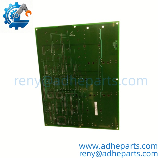
DS200KLDBG1ABC-DS215KLDBG1AZZ03A-backside
Quality Control (QC) SOP & Transparency
- Inbound Verification
- Verify and the corresponding DS215KLDBG1AZZ03A identification.
- Check the board marking and any revision/suffix information.
- Inspect LED displays, function keys, connectors, PCB traces, and mounting points.
- Check for corrosion, cracked components, burned areas, or previous solder repairs.
- Photograph all configuration jumpers before testing.
- Live Rig Testing
- Install the board in a compatible Mark V test environment where available.
- Apply the specified 24 VDC supply under controlled conditions.
- Verify display initialization.
- Test all eight function buttons.
- Check all available LED status indicators.
- Verify RS-485 inter-board communication.
- Monitor the board for abnormal resets, display loss, or intermittent communication.
- Parameter Testing
- Confirm stable 24 VDC input.
- Check current consumption against the expected low-power operating range.
- Test the complete LED display array.
- Verify button response and switch continuity.
- Check RS-485 communication stability.
- Verify configuration/jumper settings against the intended turbine application.
- Final QA & Packaging
- Record the exact board number, revision, serial information, and test results.
- Apply a QC-passed identification label.
- Place the PCB in anti-static packaging.
- Protect the LED display and function buttons from impact.
- Provide the applicable test record and a 12-month warranty under the agreed warranty terms.
Frequently Asked Questions (FAQ)
It is a display/operator-interface board for the GE Mark V Speedtronic turbine control system. It provides local display, status indication, and operator-control functions.
Q2. What is the relationship between and ?
is documented as a replacement assembly for . For procurement, I would quote both numbers together so the customer can cross-check the installed hardware.
Q3. Is this the main Mark V processor board?
No. The is primarily a display/operator-interface board. It should not be confused with the main control or processor boards in the Mark V architecture.
Q4. What is the power supply requirement?
Published technical information identifies a 24 VDC supply for the display board, with approximately 2 W power consumption.
Q5. Can this board be hot-swapped?
Do not assume it can. Mark V turbine-control cabinets contain energized control circuitry, and the safe replacement procedure depends on the specific cabinet configuration. Follow the applicable maintenance procedure and isolate power where required.
Q6. How can I confirm whether will replace my ?
Check the complete part number, board revision, cabinet location, connector arrangement, and associated Mark V hardware. A photograph of the original board’s nameplate and both sides of the PCB is the safest way to confirm the replacement.
Q7. What warranty is available?
A 12-month warranty can be provided under the agreed supply terms. For this legacy Mark V board, I would also recommend confirming the exact DS200/DS215 number and configuration before shipment.
Customers who purchased this product also viewed these products:
GE DS200DCFBG1BGB | DC2000 Power Supply Board