Description
Note: Many products are not yet listed. Please contact us for more product information. Our supply channels are constantly expanding, and we currently have 20 stable shared supply channels. Please confirm the model, product, price, and all other necessary information with customer service before placing an order. We offer new, refurbished, and used products, and prices are adjusted according to the year of the item you require.
3. Key Technical Specifications
Confirm each line against the label on your unit and the OEM datasheet. I cannot confirm the exact voltage rating and relay contact rating from the model number alone.
| Parameter | Value |
|---|---|
| Model | PW301 |
| Brand | Wattstopper (Legrand) |
| Product Family | Lighting control power pack |
| Function | Sensor power supply and load switching relay |
| Input Voltage | Verify — typically 120V AC or 277V AC; confirm on your unit label |
| Input Frequency | 50/60 Hz — verify |
| Sensor Supply Output | Low-voltage DC to occupancy sensors — verify voltage and current |
| Load Relay Type | Internal relay, latching or non-latching — verify |
| Relay Contact Rating | Verify with OEM datasheet — confirm the load rating for your fixture type |
| Load Type | Incandescent, fluorescent, LED, or motor — verify compatibility with your load |
| Sensor Compatibility | Wattstopper low-voltage sensors — verify the sensor model |
| Wiring | Line and load terminals plus low-voltage sensor leads — verify terminal arrangement |
| Mounting | Junction box or fixture — verify mounting method |
| Housing | Verify — plastic or metal enclosure |
| Operating Temperature | Verify for your installation environment |
| Storage Temperature | Verify |
| Humidity | Verify — not rated for wet locations |
| Weight | Verify with OEM documentation |
| Certifications | UL, cUL — verify on the specific unit’s label |
4. Product Introduction
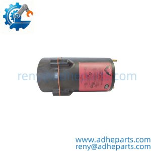
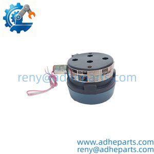
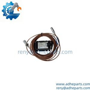
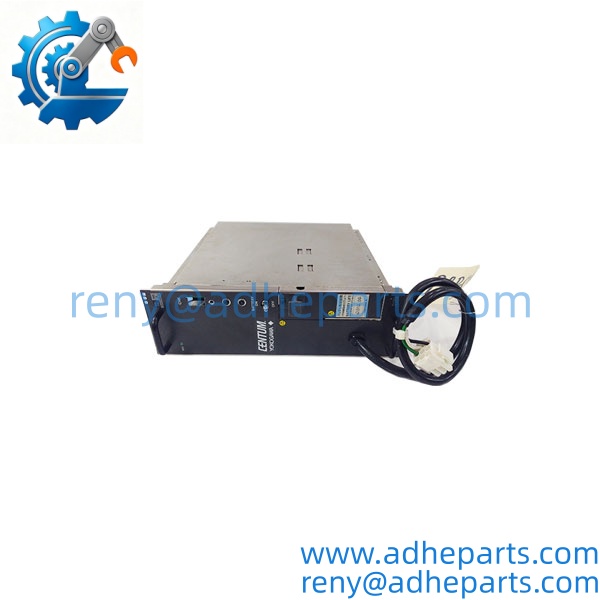
The Wattstopper PW301 is a lighting control power pack. It does two jobs in one enclosure: it supplies low-voltage DC to one or more occupancy sensors, and it switches the line-voltage lighting load through an internal relay when the sensor tells it to. The sensor itself does not carry the lighting load — the power pack does.
The engineering value is that separation. A low-voltage sensor can be mounted where it sees the space, and the power pack can sit in a junction box near the fixture, carrying the load current through short wiring. In my experience, that is what makes these units practical on a retrofit — you are not pulling heavy conductors to a ceiling-mounted sensor.
One thing to verify before you order: the voltage rating and the load type. A power pack rated for a resistive or incandescent load may not be rated for the inrush of an LED driver bank or a motor load. Check the relay contact rating against the actual load you are switching.
PW301

PW301
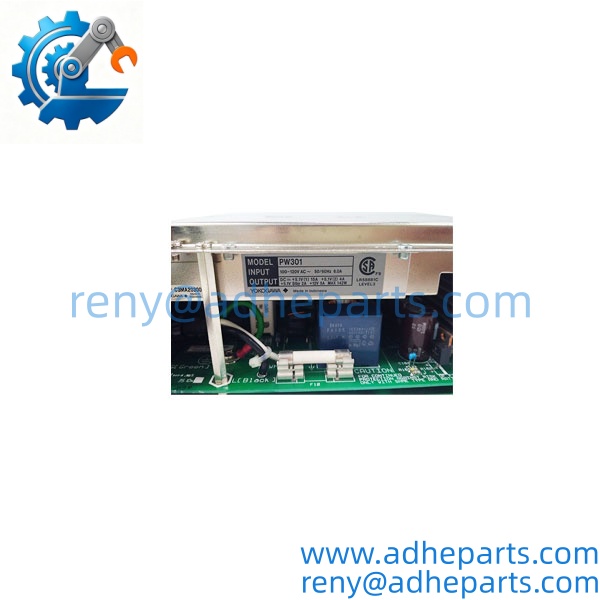
PW301

PW301
5. Application Scenarios & Field Experience
Part 1 – Narrative Paragraph
The failure that shows up most on lighting control power packs is a relay that welds closed. The lights stay on, the sensor reports “unoccupied,” and nobody notices until the energy bill or a complaint comes in. I have seen that traced to a load the relay was never rated for — an LED driver bank with a high inrush, or a motor load the contact was not designed to break. Before you replace a power pack, check the load type against the relay rating. A new unit with the same underrated relay will fail the same way.
Part 2 – Numbered List (Application Scenarios)
- Commercial Offices – Occupancy-Controlled Lighting – The power pack supplies a ceiling sensor and switches the lighting circuit in a private office or conference room. The sensor mounts where it sees the space; the pack sits in the junction box above.
- Warehouses and Storage – Aisle Lighting Control – Used with aisle or high-bay occupancy sensors to switch lighting banks on and off by zone. The relay rating matters here because high-bay fixtures draw significant inrush current.
- Restrooms and Corridors – Automatic Lighting – The pack supplies a low-voltage sensor and switches the fixture circuit. These are the highest-cycle applications, and the relay contact life is the limiting factor.
- Educational Facilities – Classroom and Gym Lighting – Used with occupancy sensors to switch lighting in spaces with irregular schedules. The pack’s mounting location makes it accessible for service without scaffolding.
Part 3 – Short Field Story
A distribution center had a row of high-bay lights that stayed on overnight for three weeks. The facility manager assumed the occupancy sensor had failed. The sensor was fine. The power pack relay had welded closed — the LED high-bay drivers had an inrush current higher than the relay was rated to break, and after a few thousand cycles the contacts stuck. We supplied a power pack with a relay rated for the actual load, and the zone went back to switching correctly. The original unit had been correctly installed and correctly wired — it was simply underrated for the fixture type.
6. Standard Operating Procedure (SOP) for Quality Control
- Visual & Origin Inspection – We verify the Wattstopper marking, the PW301 model string, and the date code. We inspect the enclosure for cracks, the terminals for corrosion, and the sensor leads for damage. A unit with a cracked housing or burned terminals is rejected.
- Voltage Rating Documentation – We read and photograph the label and confirm the input voltage rating. A unit labeled for a different voltage than requested is set aside rather than shipped.
- Relay Contact Test – We apply a resistive load to the relay contacts and verify they open and close cleanly. We check for contact resistance above the OEM limit, which indicates a relay near end of life.
- Sensor Supply Verification – We measure the low-voltage output with a sensor simulator connected. The output must stay within the OEM specification under load.
- Function Test – We verify the unit switches the load when the sensor signal is present and releases when it is removed.
- Packaging – The unit is wrapped in protective film, seated in a foam insert with the terminals protected, and packed in a carton with handling labels.
7. Frequently Asked Questions (FAQ)
Q1: What is the voltage rating of the PW301?
A: I cannot confirm the exact rating from the model number alone. Wattstopper power packs are built for different line voltages, and the label on your unit is the authority. Read the label and confirm it matches your circuit before you order. If you send us a photo of the label, we will confirm what you have.
Q2: Can I use this with any occupancy sensor?
A: No. The power pack supplies a specific low-voltage output, and the sensor must be compatible with that supply. Wattstopper low-voltage sensors are designed to work with these packs, but verify the sensor model against the OEM compatibility list. A mismatched sensor may not power up or may not signal correctly.
Q3: What load types can the internal relay switch?
A: That depends on the relay contact rating, which I cannot confirm from the model number. Incandescent, fluorescent, LED, and motor loads all have different inrush characteristics. Check the relay rating against the actual load you are switching. An underrated relay will weld closed or fail prematurely.
Q4: What is the warranty on this unit?
A: We offer a 12-month warranty from the ship date covering hardware defects — relay failure, sensor supply failure, and terminal failure under normal operating conditions. It does not cover damage from connecting the wrong line voltage, overloading the relay beyond its rating, or moisture ingress. Every unit is function-tested before it ships.
Q5: Any installation pitfalls I should watch for?
A: Four. First, verify the line voltage and the relay load rating against your circuit before you install. Second, power down the circuit at the breaker before you touch the wiring — line voltage is present at the terminals. Third, keep the low-voltage sensor leads separate from the line-voltage conductors to avoid induced noise on the sensor signal. Fourth, after installation, verify the load switches on and off with the sensor before you close up the junction box. A unit that powers up is not necessarily switching correctly.