Description
Note: Many products are not yet listed. Please contact us for more product information. Our supply channels are constantly expanding, and we currently have 20 stable shared supply channels. Please confirm the model, product, price, and all other necessary information with customer service before placing an order. We offer new, refurbished, and used products, and prices are adjusted according to the year of the item you require.
Product Introduction
When an I/P converter drifts out of calibration, modulating control valves will track poorly and introduce steady‑state offset across whole‑loop control.
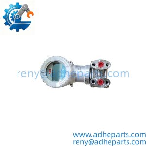
This field‑housing I/P transducer bridges electronic DCS outputs to legacy pneumatic final‑control elements. The‑S suffix adds integrated supply and output pressure gauges for local visual troubleshooting, though mounting inclination will shift zero point —though your mileage may vary depending on final installed orientation.
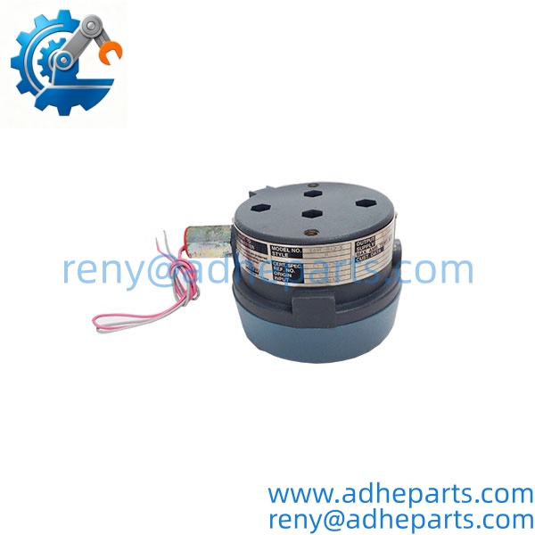
E69F‑B12‑S
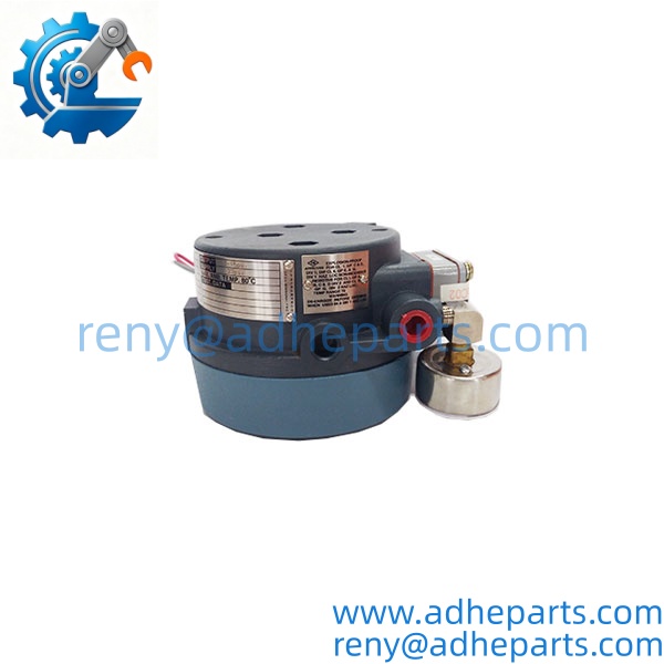
E69F‑B12‑S
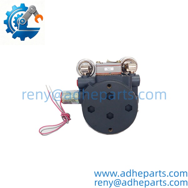
E69F‑B12‑S
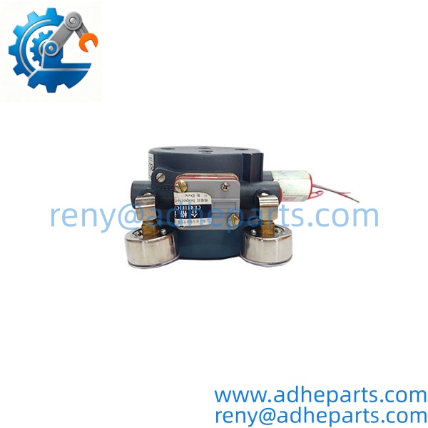
E69F‑B12‑S
Key Technical Specifications
| Parameter | Value |
|---|---|
| Input Signal | 4‑20 mA DC, 170 Ω loop impedance |
| Pneumatic Output | 3‑15 PSI (20‑100 kPa) |
| Instrument Air Supply | 20 PSI (1.4 bar nominal) |
| Enclosure Type | Bolted weather‑proof NEMA 4X / IP65 |
| Accuracy | ±1.0 % of span |
| Linearity | ±0.5 % of span typical |
| Hysteresis | ±0.5 % of span typical |
| Built‑in Hardware | Supply gauge, output gauge (‑S option) |
| Operating Temperature | 0 °C to +60 °C ambient |
| Mounting | Valve‑actuator bracket or remote surface mount |
| Action Mode | Direct acting (field‑adjustable for reverse) |
Field Application & Technical Pitfalls (The Engineer’s Guide)
This I/P converter sees regular deployment across three common process‑plant scenarios. Refinery modulating control loops translate DCS analog outputs for pneumatic globe‑valve actuators. Chemical‑plant batch‑process skids use it to throttle flow‑control valves in outdoor field locations. Water‑treatment facilities deploy these units where existing plant instrument‑air infrastructure remains in service.
Critical technical pitfalls during replacement:
- Mounting‑angle zero offset: A 5‑degree tilt away from vertical creates measurable zero drift. Calibration must happen after fastening the unit in its final physical position, not on the workbench. The lower‑left mounting lug takes the primary fastener for bracket installation.
- Contaminated instrument‑air supply: Oil, water, or particulate carry‑over clogs internal nozzle‑flapper assemblies. Even short‑term contaminated air service will produce output hunting and unstable valve response.
- Loop‑resistance mismatch: Excessive total loop resistance can restrict 4‑20 mA drive capability from the control system analog output card. Unstable input current presents as random pneumatic‑output wandering with no obvious hardware damage.
A field crew swapped a failed E69F‑B12‑S on a cooling‑water control valve. They calibrated zero‑and‑span on the maintenance bench before bolting it onto the actuator bracket, and they skipped upstream air‑filter check. Once online, the valve exhibited slow‑drifting set‑point offset that shifted as plant vibration moved the assembly. Technicians spent several hours tuning loop PID parameters before noticing the uncorrected tilt‑induced offset and water‑contaminated instrument‑air supply. Always complete zero‑span adjustment only after final mounting, and verify air‑supply filter condition upstream.
Quality Control (QC) SOP & Transparency
- Inbound Verification: Cross‑reference full part number E69F‑B12‑S, model suffix markings and serial number against OEM packaging. Inspect enclosure casting for cracks, thread damage, and gauge‑glass integrity. Confirm no scratches or dents on the two built‑in pressure gauge faces. Check for signs of prior air‑line fitting thread wear.
- Live Rig Testing: Secure unit on test fixture, apply regulated 20 PSI instrument‑air supply. Inject 4 mA, 12 mA, and 20 mA DC loop signals. Record corresponding pneumatic‑output values against target 3‑15 PSI range. Confirm both local gauges track actual test‑bench pressure readings. Check for output‑signal hunting under steady‑state input.
- Parameter Testing: Measure input‑loop impedance. Verify zero‑and‑span adjustment screw full travel range. Check air‑supply‑pressure‑effect performance by varying supply pressure across acceptable operating band. Inspect for air leakage across housing joints and threaded ports using bubble‑test method.
- Final QA & Packaging: Seal all pneumatic port threads with protective plastic plugs. Disconnect test wiring. Apply QC‑passed label with test‑run timestamp. Pack inside foam‑lined shipping container to protect gauge assemblies from mechanical shock during transit.
Frequently Asked Questions (FAQ)
Can I swap this I/P converter while the 4‑20 mA control loop stays energized?Electrical loop hot‑swap is physically possible, but not recommended. Transient current spikes can upset the host DCS analog‑output channel. Isolate the loop before wiring changes to prevent unexpected valve movement.
What exact system hardware pairs with E69F‑B12‑S?Works with any standard 4‑20 mA analog output from distributed control systems. It delivers 3‑15 PSI pneumatic output for conventional spring‑diaphragm valve actuators. Verify exact load capacity with the OEM datasheet before integration.
What warranty coverage applies for new‑surplus E69F‑B12‑S units?Twelve‑month functional warranty applies. Warranty excludes damage from contaminated instrument‑air service, improper mounting‑orientation calibration, over‑pressure air supply, or field‑side mechanical impact. Minor cosmetic casting shelf marks do not void coverage.
How do I tell genuine Foxboro OEM surplus hardware from rebuilt aftermarket copies?Genuine units carry crisp cast‑in branding, matched factory‑calibrated gauge sets, and consistent thread finish on pneumatic ports. Rebuilt units often show replaced generic pressure gauges, re‑tapped port threads, or visible disassembly marks on the bolted housing cover. Well, technically legitimate field‑repaired OEM units exist, so full bench‑range testing remains the final validation step.
Will I need to re‑calibrate after physical installation?Yes. Bench calibration does not account for mounting‑tilt offset. Always re‑run zero‑and‑span after bolting the unit into its permanent field position.
What symptoms point toward a failing E69F‑B12‑S converter in‑service?Valve‑position hunting, steady‑state control offset, inability to reach full‑scale pneumatic output, and local gauge readings that do not track expected 4‑20 mA command. These symptoms can also stem from bad instrument‑air quality or actuator‑spring fatigue, so isolate the I/P unit for bench verification.
Is E69F‑B12‑S still in OEM active production?No, this platform is officially discontinued. Once existing surplus stock depletes, sourcing lead‑times extend significantly. Confirm stock status well ahead of planned plant‑maintenance windows.