Description
Note: Many products are not yet listed. Please contact us for more product information. Our supply channels are constantly expanding, and we currently have 20 stable shared supply channels. Please confirm the model, product, price, and all other necessary information with customer service before placing an order. We offer new, refurbished, and used products, and prices are adjusted according to the year of the item you require.
3. Key Technical Specifications
Do not order against this table alone. I cannot confirm the exact input ranges, output types, and configuration from the model number. Match every line against the OEM datasheet and the label on your existing module.
| Parameter | Value |
|---|---|
| Model | SCM-1 |
| Brand | DEIF |
| Product Family | Verify — likely DEIF synchronizing control module line |
| Module Type | Synchronizing control module |
| Function | Generator-to-bus synchronization: voltage matching, frequency matching, phase angle matching, breaker close command |
| Input Voltage Sensing | Verify with OEM datasheet — confirm generator and bus voltage inputs on your unit |
| Input Frequency Range | Verify — typically 50/60 Hz nominal with a window for synchronization |
| Breaker Close Output | Verify — relay contact or transistor output; confirm contact rating |
| Voltage / Frequency Matching Outputs | Verify — raise/lower signals to the governor and AVR |
| Digital Inputs | Verify count and function (e.g., breaker status, mode select) |
| Digital Outputs | Verify count and function (e.g., sync OK, alarm) |
| Communication Interface | Verify — serial or fieldbus; confirm protocol on your unit |
| Configuration Method | Verify — potentiometers, DIP switches, or software tool |
| Power Supply | Verify — voltage range and current draw; confirm on the unit label |
| Operating Temperature | 0 °C to +55 °C (typical — verify for your switchboard) |
| Storage Temperature | –40 °C to +85 °C (typical — verify) |
| Humidity | 5% – 95% RH, non-condensing |
| Mounting | Verify — panel or DIN rail; confirm cutout and bracket |
| Weight | Verify with OEM datasheet |
| Certifications | Verify on the specific unit’s label — marine and offshore approvals may apply |
4. Product Introduction
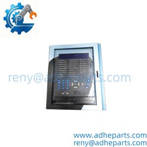
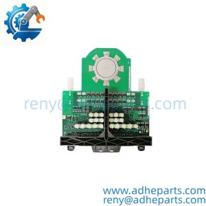
The DEIF SCM-1 is a synchronizing control module used in generator and power management systems. It monitors the generator voltage and the bus voltage, compares frequency and phase angle, and issues a breaker close command when the two sources are within the configured window. It also provides the raise/lower signals to the governor and the automatic voltage regulator to bring the generator into sync.
The engineering value is the protection against out-of-phase closing. A generator closed onto a bus with a large phase angle difference will experience a violent torque transient that can damage the coupling, the windings, or the breaker. The SCM-1 prevents that by blocking the close command until the voltage, frequency, and phase angle are all within limits. In my experience, the most common cause of a synchronization failure is not the module itself—it is a governor or AVR that is not responding to the raise/lower signals, or a voltage transformer fuse that has blown. The SCM-1 reports the condition, but it cannot fix a failed actuator.
Two things decide whether a swap works. First, the configuration. The voltage and frequency windows, the breaker close pulse length, and the raise/lower output type are all set in the module. Record the settings from the old unit before you remove it. Second, the input wiring. The generator and bus voltage inputs must be connected to the correct phases and the correct polarity, or the module will see a phase angle that does not match reality.
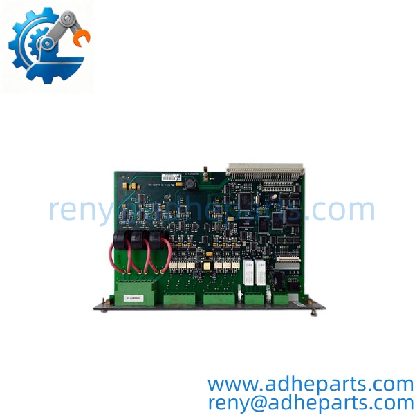
SCM-1
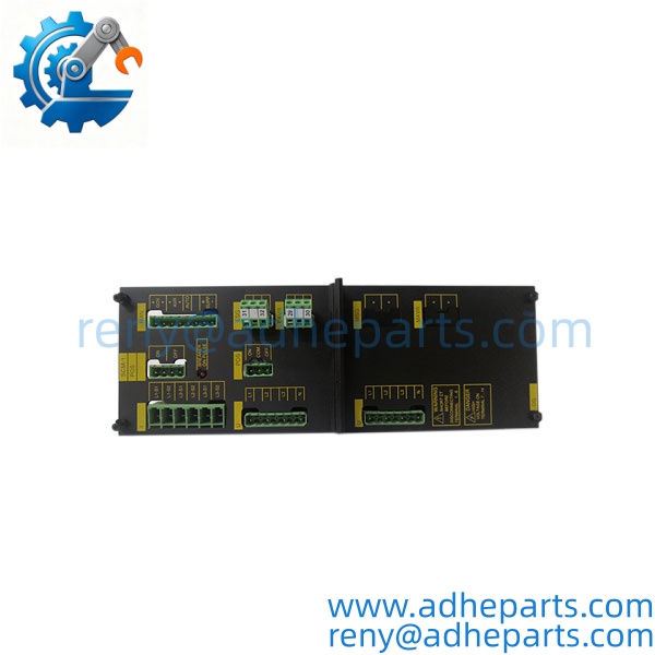
SCM-1
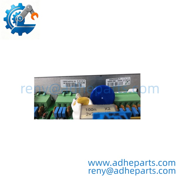
SCM-1
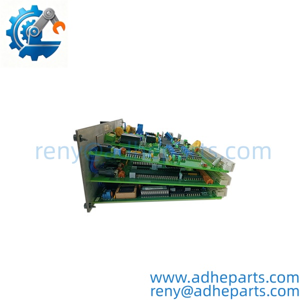
SCM-1
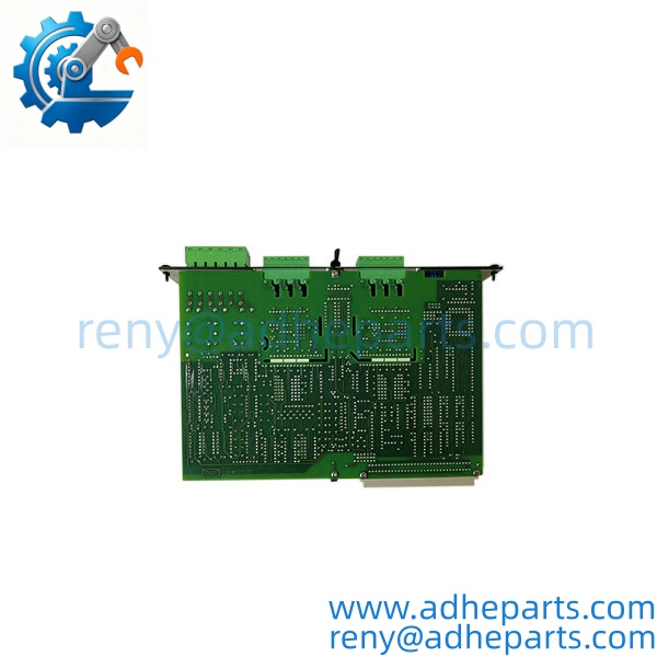
SCM-1
5. Application Scenarios & Field Experience
Part 1 – Narrative Paragraph
The failure that hurts most on a synchronizing module is a breaker close that happens out of phase. The generator is running, the operator presses the close button, and the breaker slams shut with a phase angle difference of 30 degrees. The lights flicker, the coupling takes a shock, and the breaker contacts erode. I have seen that on a vessel where the SCM-1 had a failed phase angle input and the module was issuing the close command based on voltage and frequency alone. The module was not reporting a fault—it was doing what it was configured to do with a missing signal. Before you trust a synchronizing module, verify the phase angle input and the voltage transformer fuses. A module that powers up is not necessarily synchronizing correctly.
Part 2 – Numbered List (Application Scenarios)
- Marine – Generator Paralleling on a Vessel – The SCM-1 synchronizes a diesel generator to the ship’s main bus. It matches the generator voltage and frequency to the bus and closes the breaker at the correct phase angle. The raise/lower outputs drive the governor and the AVR.
- Offshore Platforms – Power Management System – Used to parallel gas turbine generators on an offshore platform. The module interfaces with the power management system to start, synchronize, and load-share the generators.
- Industrial Plants – Emergency Generator Synchronization – The module synchronizes a standby generator to the plant bus after a utility outage. The breaker close command is blocked until the generator is within the sync window.
- Water Treatment – Cogeneration Generator Paralleling – Used to parallel a cogeneration generator with the utility feed. The module protects against out-of-phase closing and provides the raise/lower signals to the governor.
Part 3 – Short Field Story
A ferry operator had a generator that would not synchronize to the main bus. The crew had replaced the module and the fault persisted. We asked them to check the voltage transformer fuses on the bus side. One fuse was blown, and the was seeing a bus voltage that was lower than actual. The module was correctly refusing to close because the voltage mismatch was outside the window. The plant replaced the fuse, and the generator synchronized on the next attempt. The module had been fine—the voltage sensing circuit was the problem.
6. Standard Operating Procedure (SOP) for Quality Control
- Visual & Origin Inspection – We verify the DEIF marking, the model string, and the date code. We inspect the terminals, the front panel, and the housing for cracks or moisture ingress. A module with a damaged terminal or evidence of rework is rejected.
- Configuration Documentation – We read and photograph the full model string, the firmware or hardware revision, and all configuration settings where accessible (voltage window, frequency window, phase angle window, breaker close pulse length). That record ships with the module so you can compare it against the unit you are replacing.
- Power-Up Self-Test – The module is powered on a bench fixture at the specified supply voltage. We verify it initializes without a fault and that the status indicators show normal operation.
- Voltage and Frequency Input Verification – We apply calibrated voltage and frequency signals to the generator and bus inputs. We verify the module’s measured values against the reference and confirm that the sync window logic operates at the configured thresholds.
- Breaker Close Output Test – We simulate a sync condition and verify the breaker close output operates. We measure the contact closure or the output voltage and confirm the pulse length matches the configuration.
- Raise/Lower Output Test – We verify the raise and lower outputs operate when the generator voltage or frequency is outside the window. We measure the output type and confirm it matches the OEM specification.
- Isolation Test – We apply the rated isolation voltage between the input circuits and the output circuits. Leakage current must stay below the datasheet limit.
- ESD-Safe Packaging – The module is wrapped in anti-static film, seated in a conductive foam insert with the terminals protected, and packed in a double-wall carton with static warning labels.
7. Frequently Asked Questions (FAQ)
Q1: What is the function of the DEIF ?
A: The is a synchronizing control module. It matches a generator’s voltage and frequency to the bus and closes the breaker when the phase angle is within the configured window. It also provides raise/lower signals to the governor and the AVR. I cannot confirm the exact input ranges and output types from the model number alone—verify against the OEM datasheet and the label on your unit.
Q2: Can I replace an with a different DEIF synchronizing module?
A: Not without checking the input voltage ranges, the output types, and the configuration method. DEIF builds several synchronizing modules with different features and different form factors. A module with a different input range may not read your voltage transformers correctly; a module with a different output type may not drive your breaker close coil. Match the full model string and the label on your existing unit before you order.
Q3: What is the warranty on this module?
A: We offer a 12-month warranty from the ship date. It covers component failure, input sensing failure, output failure, and power supply failure under normal operating conditions. It does not cover damage from incorrect supply voltage, reversed voltage transformer wiring, or a breaker close coil that backfeeds into the output. We test every module on a bench fixture with calibrated voltage and frequency inputs before it ships.
Q4: Do you have this in stock?
A: DEIF inventory moves and varies by build. Confirm availability before you plan an outage. If we are out of the variant, we will tell you what we actually have and whether a different build would suit your system.
Q5: Any installation pitfalls I should watch for?
A: Four. First, verify the voltage transformer fuses and the wiring before you power up—a blown fuse or a reversed phase will cause the module to see a false voltage or a false phase angle. Second, record the configuration settings (voltage window, frequency window, phase angle window, breaker close pulse length) from the old module before you remove it. Third, confirm the breaker close output type and rating match your breaker close coil. Fourth, after the swap, perform a test synchronization with the generator offline or on a test bus before you attempt a live close. A module that powers up is not necessarily synchronizing correctly.