Description
Note: Many products are not yet listed. Please contact us for more product information. Our supply channels are constantly expanding, and we currently have 20 stable shared supply channels. Please confirm the model, product, price, and all other necessary information with customer service before placing an order. We offer new, refurbished, and used products, and prices are adjusted according to the year of the item you require.
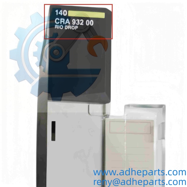
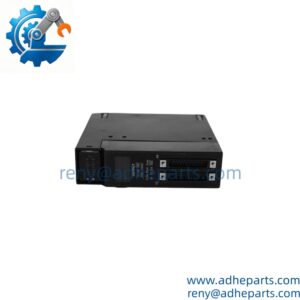
Schneider 140XBE10000
3. Key Technical Specifications
| Parameter | Value |
|---|---|
| Model | 140XBE10000 |
| Brand | Schneider Electric (Modicon) |
| Product Family | Modicon Quantum (140 series) |
| Module Type | Backplane expander / bus link module |
| Function | Extends the local Quantum backplane bus across a second (and third) rack |
| Compatible Racks | Quantum 140 series racks — 6-slot (140XBP00600), 10-slot (140XBP01000), 16-slot (140XBP01600) |
| Compatible CPUs | All Modicon Quantum CPUs; verify firmware revision supports the rack count you plan |
| Slots Occupied | 1 slot in each rack being linked (2 modules total for a 2-rack system) |
| Max Expansion Racks | Typically 2 expansion racks per CPU (3 racks total) — confirm against your CPU and rack configuration |
| Power Distribution | None. The XBE does not pass power. Each rack requires its own 140CPS power supply |
| Interconnect Cable | Not included. Separate cable required (140XCA71703 series and other lengths) |
| Backplane Bus Current (5V) | Approx. 300 – 400 mA per module — verify against OEM datasheet for your build |
| Addressing Behavior | Expanded rack I/O keeps local addressing and continues sequentially from the primary rack |
| Hot Swap | Not supported. Power down the rack before insertion or removal |
| Isolation | Bus logic isolated from chassis ground per Quantum backplane design |
| Indicators | No front-panel status LEDs; module health is reported through the CPU’s I/O status |
| Operating Temperature | 0 °C to +60 °C |
| Storage Temperature | –40 °C to +85 °C |
| Humidity | 0% – 95% RH, non-condensing |
| Dimensions (W x H x D) | Approx. 40.3 mm x 250 mm x 103.9 mm (single-width Quantum module) |
| Weight | Approx. 0.3 kg (0.66 lb) |
| Certifications | UL 508, CSA C22.2 No. 142, CE, FM Class I Div 2 (verify on the specific unit’s label) |
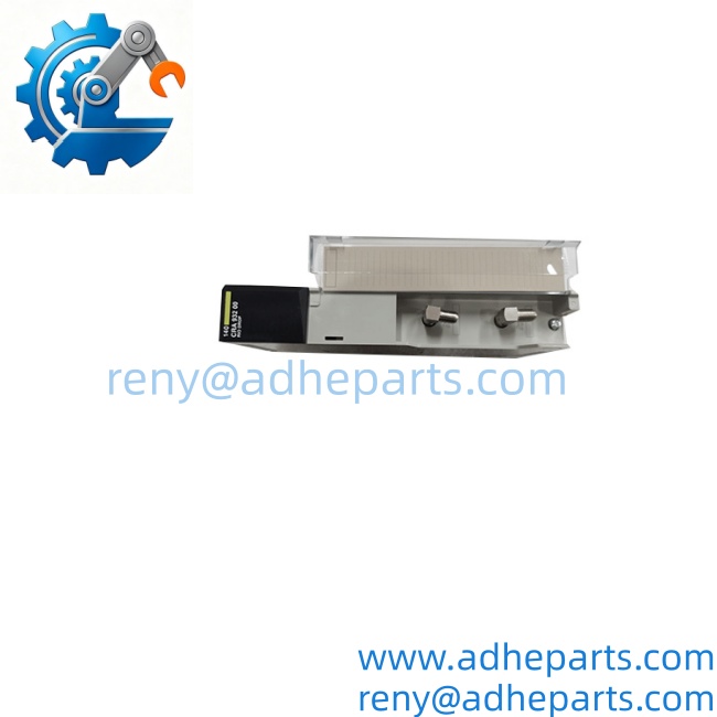
Schneider 140XBE10000
4. Product Introduction
The Schneider Electric 140XBE10000 is a backplane expander module for the Modicon Quantum platform. It does one job: it carries the local backplane bus from a primary Quantum rack into a second rack, so the CPU sees the expansion rack’s I/O as part of its own address space. You install one XBE in the primary rack and one in the expansion rack, tie them together with the interconnect cable, and the I/O map grows without a new CPU or a network drop.
Two engineering facts decide whether this part is right for your job. First, the XBE carries bus signals only—it does not distribute power. Every rack in the chain needs its own 140CPS supply module. Second, the interconnect cable is a separate line item. I have watched a crew install two XBE modules, torque the terminal blocks, and then discover there is no cable in the box. Order it with the modules, not after.
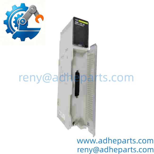
Schneider 140XBE10000
5. Application Scenarios & Field Experience
Part 1 – Narrative Paragraph
The problem this module solves is slot starvation. A 10-slot Quantum rack fills up fast once you add a CPU, a power supply, a couple of communication modules, and a handful of analog cards. When the process engineer comes back wanting eight more I/O points, the choices are ugly: add a remote drop with a network interface (new addressing, new configuration, new troubleshooting surface), or rip out the whole rack and buy a bigger chassis. The XBE gives you a third option. Put a second 10-slot rack in the same cabinet, power it with its own CPS, link the two with the expander modules, and the CPU picks up the new cards at the next sequential addresses. From a programming standpoint, nothing changed. That matters at 6 AM on a Sunday when you are trying to bring a line back up.
Part 2 – Numbered List (Application Scenarios)
- Water / Wastewater – Plant Expansion Panels – A 16-slot rack running intake screens and clarifier controls was full. Adding four analog cards for new turbidity and flow transmitters required a second rack. The XBE link kept all I/O local to the CPU, so the existing ladder logic and register mapping stayed untouched.
- Metal Processing – Mill Stand Control Cabinets – Two cabinets separated by a walkway share one Quantum CPU. One XBE in each cabinet links the racks through a routed interconnect cable. The alternative—a remote I/O drop over a network—would have added a communication module and a scan-time penalty to a loop running at 20 ms.
- Oil & Gas – Compressor Station Retrofit – A station with a full 10-slot rack needed additional digital inputs for new ESD valve position feedback. The XBE expansion rack went into the same enclosure, and because both racks sit on the same station battery, the separate power supplies draw from a common DC bus.
- Pulp & Paper – Stock Preparation Line – Wet-end I/O is distributed across two enclosures to keep field cable runs short. The XBE link preserves a single CPU image, so maintenance carries one program file and one spare set of modules instead of two of everything.
Part 3 – Short Field Story
A food processing plant in the Midwest had a Quantum rack with no spare slots and a maintenance backlog of four needed analog inputs for new temperature transmitters on a pasteurizer. Their integrator quoted a remote drop with a network adapter—six weeks of programming and a new panel. We supplied two 140XBE10000 modules, the interconnect cable, and a 140CPS supply for the second rack. The plant electrician mounted the new 6-slot rack below the existing one, landed the transmitter wiring, and powered up. The CPU recognized the new cards on the first scan. Total downtime: one 4-hour maintenance window, not six weeks.
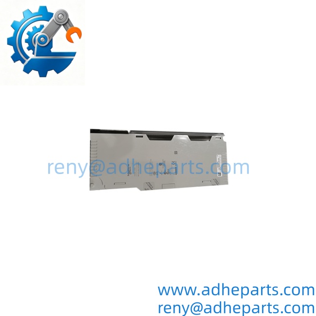
Schneider 140XBE10000
Schneider 140XBE10000
6. Standard Operating Procedure (SOP) for Quality Control
Every 140XBE10000 module passes this QC sequence before it ships:
- Visual & Origin Inspection – We verify the Schneider Electric marking, the 140XBE10000 part number, and the date code on the housing. We inspect the backplane connector for bent or recessed pins and check the retaining screw threads. Units with cracked housings or evidence of forced insertion are rejected.
- Connector Continuity Test – We buzz out every backplane pin against the OEM pinout to confirm no open traces or shorts between adjacent contacts. This catches the most common failure mode on surplus XBE modules.
- Rack Fit Verification – Each module is physically inserted into a Quantum test rack to confirm it seats fully and the retention screw engages. A module that fits loosely will cause intermittent bus faults in the field, so we reject anything with a worn connector shroud.
- Live Backplane Test – Two modules are installed in a two-rack test setup with a known-good Quantum CPU and power supplies in both racks. We download a test program that reads and writes to an I/O card in the expansion rack and confirm the data transfers cleanly.
- Bus Stability Test – The test rig runs a continuous read/write loop against the expansion rack for one hour. We log any bus errors or I/O faults. Zero errors is the pass criterion.
- Cable Interface Check – We mate and unmate the interconnect cable connector ten times on each module to confirm the latching mechanism holds and the contacts do not deform. A loose cable connection is a nuisance fault that is hard to diagnose on site.
- ESD-Safe Packaging – The module is wrapped in anti-static film, placed in a conductive foam insert with the connector protected by a rigid shroud, and packed in a double-wall carton with static warning labels.
7. Frequently Asked Questions (FAQ)
Q1: Does the 140XBE10000 pass power from the primary rack to the expansion rack?
A: No, and this is the number one mistake people make with this module. The XBE carries bus signals only. The expansion rack needs its own 140CPS power supply module, sized for the I/O cards you install in it. If you skip the second power supply, the expansion rack will not come up and the CPU will report a bus fault.
Q2: Is the interconnect cable included with the module?
A: No. The cable is a separate part. You need one cable per rack link, ordered at the length that matches your cabinet layout. Measure the actual cable route before ordering—include the vertical drops and any service loops. We can supply the cable alongside the modules if you tell us the rack spacing.
Q3: How many racks can I link, and what is the maximum cable length?
A: Most Quantum systems support a primary rack plus two expansion racks, so you would need three XBE modules for a three-rack system—one in each rack. The maximum interconnect cable length and the exact rack count depend on your CPU model and firmware revision. Verify both against the OEM installation guide before you commit to a layout. If you send us your CPU part number, we can point you to the right table.
Q4: What is the warranty, and what does it cover?
A: We offer a 12-month warranty from the ship date. It covers backplane connector failure, internal trace faults, and mechanical failure of the module housing under normal installation and operating conditions. It does not cover damage from hot-swapping the module with the rack energized, bent pins from forced insertion, or physical damage to the housing. Every module ships with a test report from our two-rack live bus test.
Q5: Any installation pitfalls I should watch for?
A: Four. First, power down both racks before inserting or removing an XBE. These modules are not hot-swap capable, and live insertion can arc the backplane pins. Second, slot placement matters—the primary rack and the expansion rack do not use the same slot position. Follow the OEM installation guide rather than guessing. Third, route the interconnect cable away from VFD output wiring and motor leads; the backplane bus is not designed to reject the noise those cables radiate. Fourth, if the CPU does not see the expansion rack’s I/O after power-up, check the cable orientation first—a reversed connector is the most common cause of a “no rack” fault.
Pre:Schneider Electric 140SAI94000S | TÜV Rheinland Certified Process Safety Monitoring Module
Next: