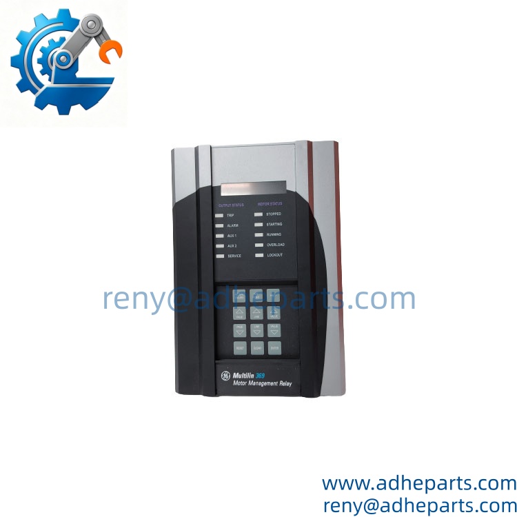
Description
Key Technical Specifications
| Parameter | Value |
|---|---|
| Product Type | Motor Management and Protection Relay |
| Series | GE Multilin 369 |
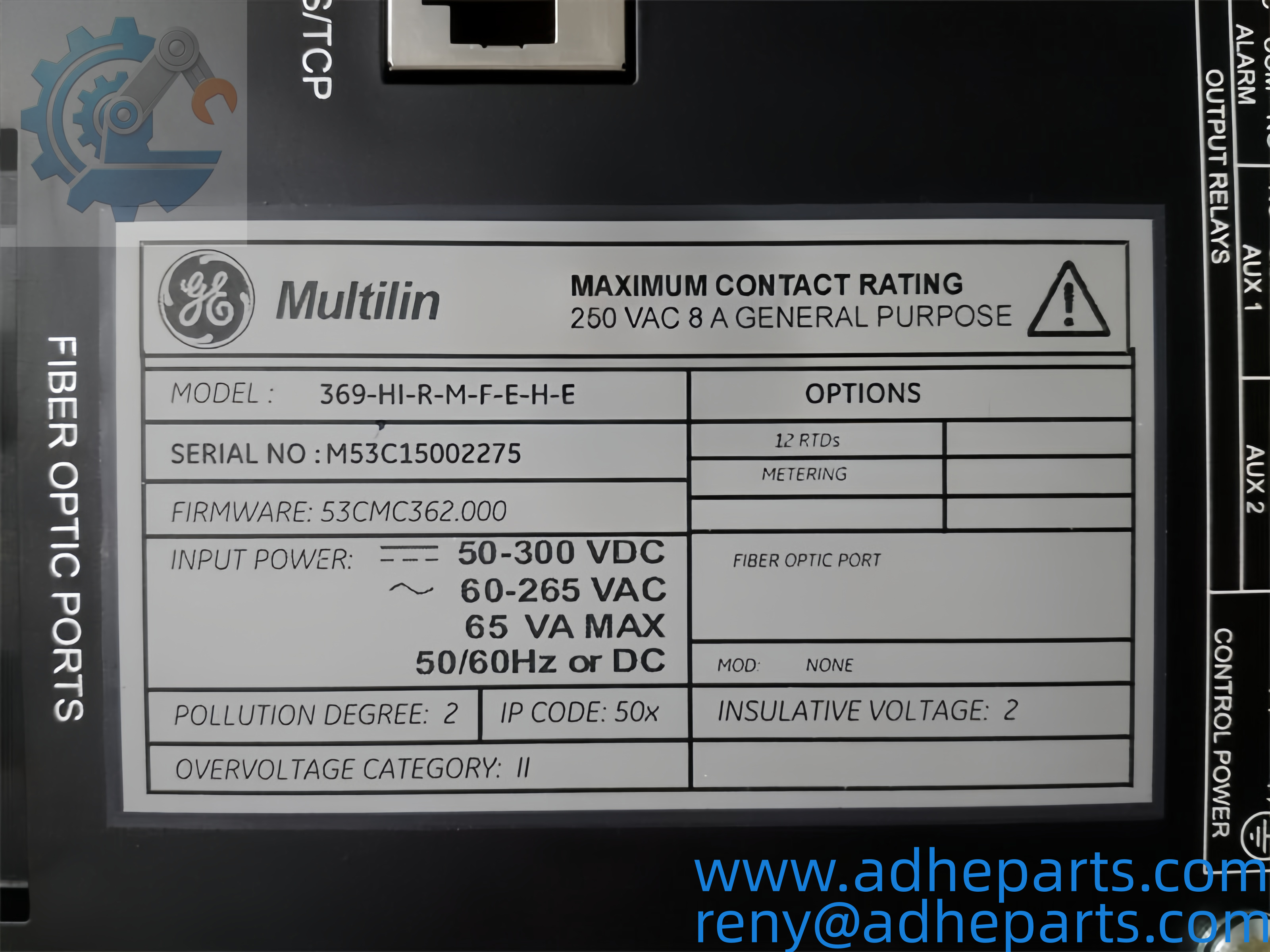
| Model | 369-H1-R-M-F-E-H-E |
| CT Inputs | 1 A or 5 A CT secondary inputs |
| Voltage Inputs | Supported when the applicable voltage/VT option is fitted |
| RTD Inputs | Up to 12 RTD channels, depending on configuration |
| Digital Inputs | Six optically isolated dry-contact inputs |
| Relay Outputs | Five Form-C and one Form-A output contacts |
| Communication | Front RS-232; rear RS-485 Modbus RTU |
| Analog Outputs | Programmable analog outputs on applicable configurations |
| Frequency | 45–65 Hz nominal |
| Operating Temperature | Approximately −40°C to +60°C, configuration dependent |
The 369 platform supports motor protection functions including thermal overload, phase-related protection, stall/jam protection, ground-fault monitoring, motor starting supervision, metering, event recording, and diagnostic functions. Exact I/O and communication features must be checked against the complete order code before replacement.
Product Introduction (Anti-Template)
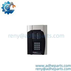
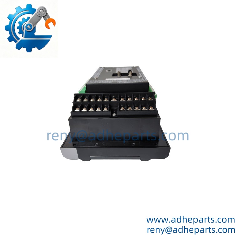
Operating as the protection and monitoring point for an industrial AC motor, the GE Multilin 369-H1-R-M-F-E-H-E combines electrical measurements, thermal modeling, programmable control logic, and communication functions in one relay. Its 369 Series architecture is intended for motor applications where a simple overload relay is not enough.
The important part during replacement is not just matching the front label. CT ratios, control power, RTD configuration, communications, and stored protection settings all need to agree with the existing installation. Honestly, checking the complete suffix before shipment can save hours of panel rewiring and commissioning work.
QC, Procurement & Logistics SOP
- Inbound Verification
- Confirm the complete model number, suffix configuration, nameplate data, and serial information against the procurement requirement.
- Check housing condition, terminal blocks, labels, accessories, and visible manufacturing markings.
- Where applicable, inspect OEM packaging and factory seals before the unit enters inventory.
- Live Rig Testing
- Perform controlled power-on inspection when the available test configuration permits.
- Check startup behavior, display/HMI response, status indicators, communication interfaces, and applicable I/O.
- For replacement-critical orders, compare the existing relay configuration with the proposed unit before dispatch.
- Do not apply field CT circuits directly during a bench test unless the test procedure specifically requires it.
- QA & Anti-Static Packaging
- Record product photographs and identification data before packing.
- Protect terminals, connectors, and exposed electronic surfaces against electrostatic discharge.
- Use anti-static protection together with shock-absorbing export packaging.
- For high-value relay shipments, the packing method should account for vibration and impact during air or sea transportation.
- Global Logistics & Export Compliance
- Confirm the commercial invoice, packing list, declared product description, country of origin, and HS classification before shipment.
- Use the most appropriate HS classification based on the actual product and destination-country customs requirements rather than relying on a generic description.
- Secure the relay inside the carton to prevent movement during transportation.
- Air freight is normally suitable for urgent outage work; sea freight can be considered for consolidated or less time-sensitive shipments.
- Customs clearance in some countries can add several working days, so document accuracy should be checked before cargo pickup.
Technical Pitfalls & Integration Warnings
1. Firmware Revision Mismatch
A replacement relay can have the same model number while carrying a different firmware revision. For example, an existing installation may have been engineered around one protocol or parameter structure while the replacement carries a later revision. If the DCS or commissioning software cannot interpret the expected data correctly, communication may drop even though the relay powers up normally.
2. DIP Switch / Configuration Errors
Do not assume the replacement can simply be plugged in and left with factory settings. Communication addresses, termination, CT ratios, input assignments, protection parameters, and other configuration items must match the application. A wrong CT ratio is particularly serious because the relay may calculate motor current incorrectly and produce inappropriate protection behavior.
3. Wiring and Terminal Compatibility
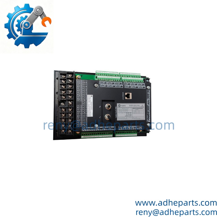
A physically identical relay does not automatically mean identical field wiring. Check the terminal arrangement, control-voltage range, CT connections, ground CT arrangement, RTD wiring, output contacts, and communication terminals before installation. Honestly, comparing the terminal drawing before removing the old unit is one of the cheapest ways to avoid a commissioning delay.
4. ESD Damage During Unboxing
Electronic protection relays can be damaged by electrostatic discharge before they are even powered. Keep the unit in its anti-static packaging until the installation area is ready, use appropriate ESD precautions, and avoid touching electronic contacts unnecessarily. A relay that passes visual inspection can still suffer latent ESD damage.
Frequently Asked Questions (FAQ)
Q1: How quickly can you ship the GE 369-H1-R-M-F-E-H-E?
If the exact configuration is physically available, dispatch can normally be arranged after order confirmation and pre-shipment inspection. The actual lead time depends on stock status, testing requirements, destination, and shipping method.
Q2: Can you arrange international air or sea freight?
Yes. The unit can be prepared for international air or sea transportation. For urgent plant maintenance, air freight is generally the practical choice; for consolidated non-urgent cargo, sea freight may be more economical.
Q3: Is this relay suitable as a direct replacement?
Potentially, but the complete configuration must be compared first. Check:
- Complete model and option suffix
- Control power
- CT input rating
- RTD configuration
- Digital and relay I/O
- Communication interface
- Firmware and existing configuration
The same 369 Series family does not guarantee that every configuration is electrically interchangeable.
Q4: Can the 369 be hot-swapped while the motor is running?
Do not treat it as a routine hot-swap operation. CT circuits can generate dangerous voltages if incorrectly opened, and removing a protection relay can also disable critical motor protection. Follow the plant’s isolation, switching, and commissioning procedure before replacement.
Q5: Will an older 369 installation accept a newer replacement?
Backward compatibility depends on firmware, hardware revision, option configuration, communication requirements, and the existing control-system integration. If the relay communicates with a DCS or PLC, verify the protocol and parameter mapping before ordering rather than assuming compatibility from the model family alone.
Q6: What information should I provide before ordering?
For a replacement-critical order, provide the complete existing nameplate/model number and, where possible, a clear photograph of the relay label and terminal area. If available, also provide the existing configuration file, firmware information, control-voltage requirement, CT ratio, RTD arrangement, and communication protocol.
Q7: Can the unit be tested before shipment?
A pre-shipment inspection can include model verification, visual inspection, power-on checks, display/status verification, and applicable communication or I/O checks. The exact test scope depends on the available test setup and the configuration of the relay.
Previous product:
ABB 3BHE022294R0101 3BHE020356R0101 GF D233A Gate Drive Unit Board