Description
Note: Many products are not yet listed. Please contact us for more product information. Our supply channels are constantly expanding, and we currently have 20 stable shared supply channels. Please confirm the model, product, price, and all other necessary information with customer service before placing an order. We offer new, refurbished, and used products, and prices are adjusted according to the year of the item you require.
Key Technical Specifications
| Parameter | Specification |
|---|---|
| Manufacturer | LENZE |
| Model | EPL10200-W |
| Product Family | EPL10200 |
| Device Type | Drive PLC |
| Supply Voltage | 24 VDC |
| Digital Inputs | 8 |
| Digital Outputs | 4 |
| Digital Output Rating | Up to 1 A per output, depending on configuration |
| Analog Inputs | 3 |
| Analog Input Range | ±10 V |
| Analog Input Resolution | 10 bits + sign |
| Analog Output | 1 |
| Analog Output Range | ±10 V / ±20 mA |
| System Bus | CAN |
| Programming Standard | IEC 61131-3 |
| Programming Environment | Lenze Drive PLC Developer Studio |
| Expansion | Extension boards available for compatible EPL10200 versions |
| Product Status | Legacy / discontinued |
The published EPL10200 specifications identify 8 digital inputs, 4 digital outputs, 3 analog inputs, and 1 analog output. Lenze’s programming documentation also shows the EPL10200 as a Drive PLC supported by its PLC development environment and system-bus documentation.
The analog-input documentation specifies the integrated AI3 channel as -10 V to +10 V with 10-bit plus sign resolution, while the general product data identifies the analog interface as 3 inputs / 1 output.
Product Introduction (Anti-Template)
The LENZE EPL10200-W belongs to the Drive PLC family, combining programmable logic, local I/O, and drive-system communication in a compact controller. It was designed for applications where machine sequencing and drive-related control need to be handled close to the motion system rather than through a separate general-purpose PLC. The basic provides 8 digital inputs, 4 digital outputs, 3 analog inputs, and 1 analog output from its 24 VDC-powered controller platform.
One important distinction for procurement: is a Drive PLC, not simply a frequency inverter. Some secondary listings describe -W as a servo drive or inverter and publish unrelated motor-drive ratings. Those descriptions should not be used to substitute a conventional Lenze inverter for an PLC. The actual control program, I/O configuration, hardware version, and connected drive architecture need to be checked before replacement.
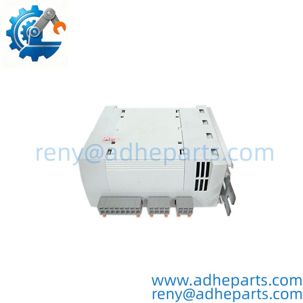
EPL10200-W
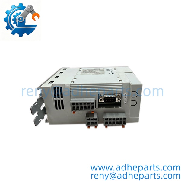
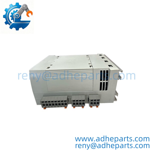
EPL10200-W
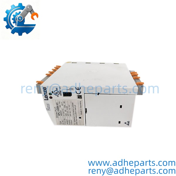
EPL10200-W
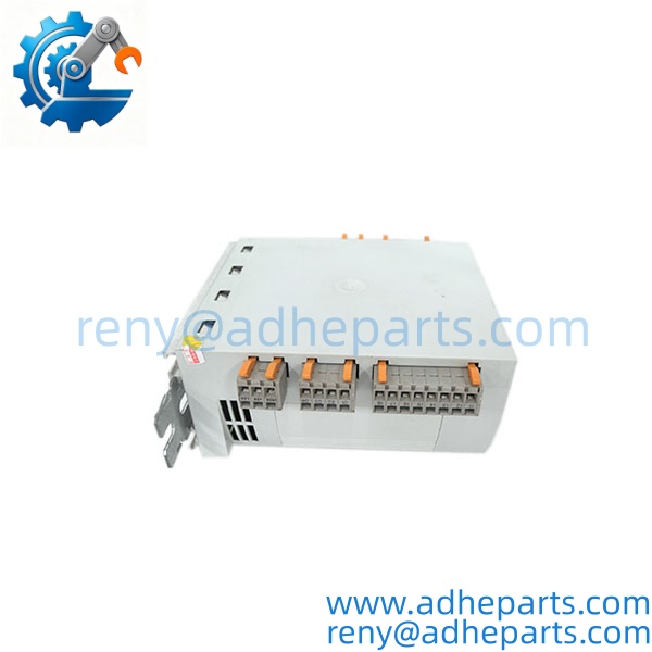
EPL10200-W
QC, Procurement & Logistics SOP
1) Inbound Identification
Verify the complete marking on the unit:
- LENZE
- -W
- family designation
- Hardware version
- Software/firmware information where available
- Serial/product number
Lenze documentation uses the EPL1020x-EI designation structure to distinguish without an extension board from EPL10201 with an extension board. The hardware and software versions are also part of the identification information.
For a replacement order, request a clear nameplate photograph rather than matching only the basic family number.
2) Power-Up Verification
The basic is specified for 24 VDC operation. During bench testing, verify the correct DC supply and inspect the power terminals before energizing the controller.
Check:
- Power-up behavior
- Status/diagnostic indication
- Controller initialization
- I/O availability
- Communication interface
- Fault indications
Do not apply AC mains voltage directly to the PLC. It is a 24 VDC controller.
3) I/O Verification
Where suitable test equipment is available, verify the integrated I/O:
- 8 digital inputs
- 4 digital outputs
- 3 analog inputs
- 1 analog output
For analog channels, use a controlled signal source and verify scaling in the PLC configuration rather than checking only whether the terminal produces a voltage.
The analog input specification should be matched against the actual hardware documentation, particularly when replacing an older unit with a different hardware revision.
4) Program and Software Compatibility
The is a programmable controller. A replacement hardware unit does not automatically contain the customer’s original application program.
Before replacement, determine:
- Existing PLC program
- Software version
- Hardware version
- Parameter set
- I/O configuration
- CAN/system-bus configuration
- Connected drive configuration
Lenze documentation shows different generations of Drive PLC software and hardware versions, so software compatibility should be checked before commissioning.
5) Communication and Drive-System Verification
The supports Lenze drive-system communication through the integrated system bus. Relevant Lenze documentation specifically covers the CAN system bus for Drive PLC devices including .
Before replacing a controller, record:
- CAN node arrangement
- Node addresses
- Baud rate
- Connected Lenze drives
- Process-data mapping
- Parameter communication
- Any installed communication module
A communication fault after replacement is not necessarily a hardware failure; an incorrect node address or process-data configuration can produce the same symptom.
6) ESD and Packaging
Protect the PLC from static discharge during handling.
For export shipment:
- Place the controller in an antistatic bag
- Protect terminal connectors
- Add shock-absorbing material
- Prevent moisture ingress
- Use a rigid export carton
- Keep the unit separated from loose metal components
7) Export & Logistics
For commercial documentation, identify the item as a LENZE -W Drive PLC / industrial programmable controller and include the complete part number.
HS classification should be confirmed according to the actual product configuration and destination customs requirements. A generic drive or inverter HS code should not be copied simply because some online sellers categorize under “drives.”
For international shipments, EXW, FCA, or DAP can be used depending on the buyer’s freight and customs arrangement. Import VAT, duty, brokerage, and customs clearance remain subject to the destination country.
For urgent production-line replacement, separate physical stock availability from tested and ready-to-dispatch status when quoting lead time.
Technical Pitfalls & Integration Warnings
1) Do Not Confuse -W with a Frequency Inverter
This is the most important point for this model. Lenze identifies as a Drive PLC. It executes application logic and handles I/O and drive-system communication; it should not be replaced based on a generic motor-inverter specification such as kW, output frequency, or motor current alone.
2) Software Compatibility Matters
Two units may be physically similar while carrying different hardware/software generations. Lenze’s documentation covers multiple software versions for the Drive PLC family. Confirm the installed engineering environment and application program before commissioning.
3) Extension Board Configuration
The family can be configured with extension hardware. Lenze documentation describes extension boards that add additional digital, analog, and encoder-related I/O. Do not assume the basic configuration has the same I/O capacity as an EPL10201 or an installation equipped with an extension board.
4) CAN/System-Bus Parameters
If the controller communicates with other Lenze drive equipment through the system bus, check node addresses, baud rate, process-data mapping, and communication parameters before replacing the PLC. A new controller with default settings may power up normally but fail to control the connected drives.
5) Analog Signal Scaling
The integrated analog channels are part of the PLC application. Check whether the existing program expects ±10 V signals, current signals, or a particular normalized engineering-unit scaling. Replacing the controller without restoring the original application configuration can produce incorrect process values even when the hardware is functioning normally.
6) Do Not Assume a Modern Lenze Controller Is a Drop-In Replacement
The is a legacy platform. A newer Lenze controller may provide more processing capability, but migration can involve software conversion, I/O remapping, communication changes, and application-program modification. For an existing machine, a like-for-like replacement is a different procurement decision from a complete controls migration.
Frequently Asked Questions (FAQ)
Q1. What is th?
It is a Drive PLC, a compact programmable controller designed for integrated drive and automation applications. It combines PLC logic, local I/O, and drive-system communication.
a servo drive or frequency inverter?
No. Its primary classification is Drive PLC. Some third-party listings incorrectly d as a servo drive or frequency inverter, but Lenze’s own documentation identifies the family as Drive PLC hardware.
Q3. How many I/O points does the basic provide?
The basic unit provides 8 digital inputs, 4 digital outputs, 3 analog inputs, and 1 analog output. Extension hardware can increase the available I/O in compatible configurations.
Q4. What power supply does use?
The basic is a 24 VDC PLC system. Confirm the actual nameplate and installation documentation before applying power.
Q5. Does support CAN communication?
Yes. Lenze documentation specifically covers the CAN system bus for Drive PLC devices including . The actual communication configuration depends on the connected drive system and application program.
Q6. Does a replacement automatically contain my machine program?
No. The controller hardware and the customer’s application program are separate considerations. Before replacement, obtain a backup of the PLC program, parameters, I/O configuration, and communication settings where possible.
Q7. What should I provide when reques replacement?
Provide the complete marking, nameplate photograph, hardware/software version, serial or product number, and a photo of any connected extension board. If available, also provide the existing PLC program and the connected Lenze drive model numbers.
Q8. How sh be tested before shipment?
A suitable test should verify 24 VDC power-up, controller initialization, diagnostic status, integrated I/O, and communication functions. If the customer’s application program is available, loading it into a compatible test environment provides a much more meaningful check than a simple power-on test.