Description
Note: Many products are not yet listed. Please contact us for more product information. Our supply channels are constantly expanding, and we currently have 20 stable shared supply channels. Please confirm the model, product, price, and all other necessary information with customer service before placing an order. We offer new, refurbished, and used products, and prices are adjusted according to the year of the item you require.
3. Key Technical Specifications
Confirm each line against the OEM datasheet and the label on your existing unit before ordering. The UMC100 family includes several variants, and the communication protocol and current range depend on the build.
| Parameter | Value |
|---|---|
| Model | UMC100 |
| Brand | ABB |
| Product Family | Universal Motor Controller (UMC) |
| Function | Motor protection, control, and monitoring |
| Current Measurement | Integral current transformers — verify the current range on your unit label |
| Rated Operational Voltage | Verify with OEM datasheet — confirm on the unit label |
| Control Voltage | 24V DC — verify on the unit label |
| Digital Inputs | Verify count and function |
| Digital Outputs | Verify count and contact rating |
| Analog Inputs | Verify — confirm thermistor and PT100 inputs on your build |
| Communication | Fieldbus via add-on module — verify the module fitted to your unit |
| Supported Fieldbuses | Profibus DP, Modbus RTU, DeviceNet, Ethernet — verify the fitted module |
| Mounting | DIN rail or UMC baseplate — verify the mounting kit |
| Operating Temperature | 0 °C to +55 °C (typical — verify for your MCC ambient) |
| Storage Temperature | –40 °C to +85 °C (typical — verify) |
| Humidity | 5% – 95% RH, non-condensing |
| Certifications | CE, UL, CSA — verify on the specific unit’s label |
4. Product Introduction
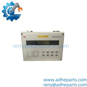
The ABB UMC100 is a universal motor controller for low-voltage motors. It provides motor protection, control, and monitoring in a single device, and it communicates with the control system over a fieldbus via an add-on module. It is the device that replaces a traditional overload relay, a contactor control circuit, and a set of discrete status signals in a motor control center.
The engineering value is the integrated motor management. The UMC100 measures current directly, accepts thermistor and PT100 inputs, and reports the motor status and the trip cause over the fieldbus. That means the operator sees which motor tripped and why, instead of a generic overload alarm. In my experience, the most common integration issue is not the controller itself — it is the current range setting and the fieldbus module configuration. Check both before you swap the unit.
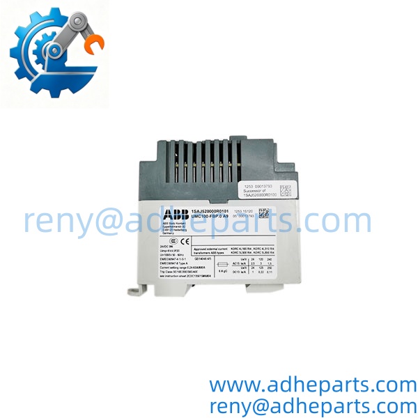
UMC100
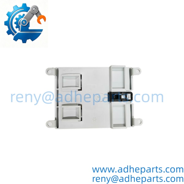
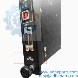
UMC100
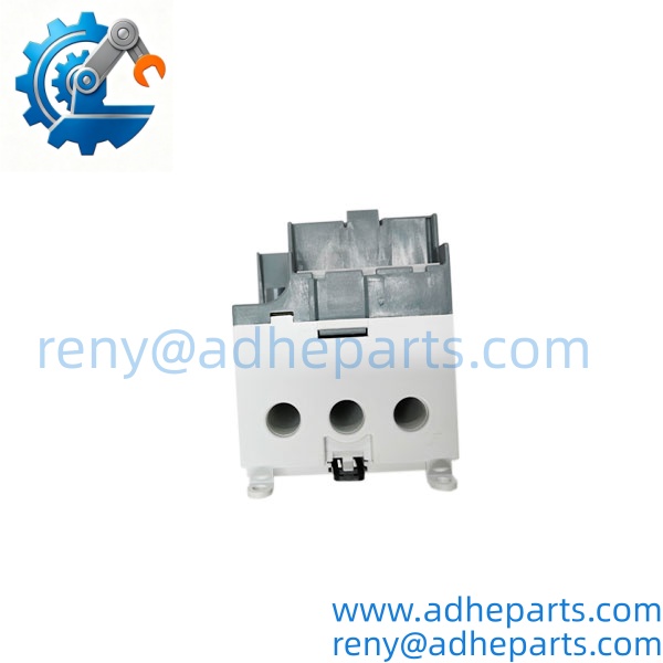
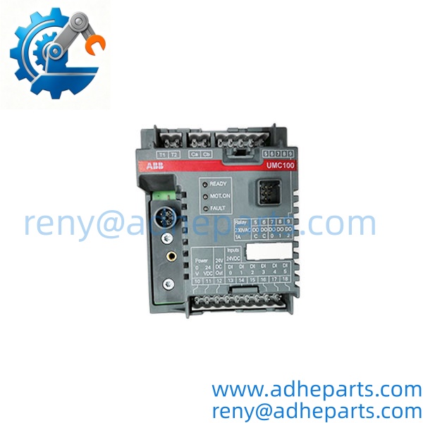
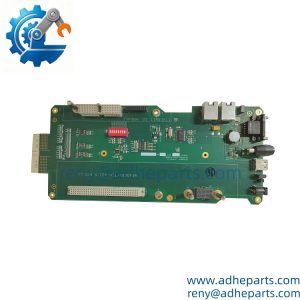
UMC100
5. Application Scenarios & Field Experience
Part 1 – Narrative Paragraph
The failure that wastes the most time on a motor control center is not a dead motor — it is a trip with no clear cause. The overload relay has tripped, the reset button has been pressed, and nobody knows whether the motor is overloaded, the cooling is blocked, or the winding is failing. The UMC100 solves that by logging the trip cause and reporting it over the fieldbus. The maintenance team sees the actual condition instead of a generic fault. I have used that data to catch a blocked fan on a pump motor before the winding failed.
Part 2 – Numbered List (Application Scenarios)
- Water Treatment – Pump Motor Management – The UMC100 protects and controls a pump motor, monitors the current and the thermistor, and reports the status to the SCADA system over Profibus DP. The trip cause is logged and displayed.
- Oil & Gas – Compressor Motor Control – Used on a low-voltage compressor motor in a motor control center. The fieldbus module connects the controller to the plant network, and the integral current measurement provides the overload protection.
- Material Handling – Conveyor Motor Control – The controls a conveyor motor and monitors the current for a jam condition. The digital inputs accept the local start/stop and the safety circuit.
- HVAC – Fan and Pump Motor Protection – Used in a building automation panel to protect and monitor fans and pumps. The PT100 input monitors the motor winding temperature.
Part 3 – Short Field Story
A water treatment plant had a pump motor that would trip on overload every few weeks. The crew had replaced the motor and the starter, and the trips continued. We connected the ’s fieldbus module and logged the trip data. The current was rising gradually before each trip, and the thermistor input showed a temperature increase that the overload relay had not seen. The cause was a blocked cooling fan on the motor. The plant cleaned the fan and the trips stopped. The had turned a recurring mystery into a specific maintenance item.
6. Standard Operating Procedure (SOP) for Quality Control
- Visual & Origin Inspection – We verify the ABB marking, the model string, and the date code. We inspect the terminals, the current transformers, and the housing for damage or moisture ingress. A unit with a damaged terminal or a cracked housing is rejected.
- Variant Documentation – We read and photograph the full model string and record the fieldbus module fitted and the current range setting. That record ships with the unit so you can compare it against the unit you are replacing.
- Power-Up Self-Test – The unit is powered on a bench fixture at rated control voltage. We verify it initializes without a fault and that the status indicators show normal operation.
- Current Measurement Verification – We inject a calibrated current through the integral transformers and verify the measured value against the reference across the range.
- Digital I/O Verification – We exercise each digital input and output and verify the unit responds correctly.
- Fieldbus Communication Test – We verify the fitted fieldbus module with a test master and confirm the address and protocol settings. We record the configuration.
- Thermistor and PT100 Input Test – We connect a calibrated simulator to each temperature input and verify the reading against the reference.
- ESD-Safe Packaging – The unit is wrapped in anti-static film, seated in a foam insert with the terminals protected, and packed in a double-wall carton with static warning labels.
7. Frequently Asked Questions (FAQ)
Q1: What fieldbus module is fitted to this ?
A: I cannot confirm the fitted fieldbus module from the base model number alone. The family uses add-on modules for Profibus DP, Modbus RTU, DeviceNet, and Ethernet, and the module on your unit is marked on the label or the module itself. Read the marking before you order. A unit with a different fieldbus module will not communicate with your control system.
Q2: What is the current range of this controller?
A: The uses integral current transformers, and the range depends on the build. Check the label on your existing unit for the rated current range. A controller with a different range will not measure the motor current correctly or will not protect the motor properly.
Q3: What is the warranty on this unit?
A: We offer a 12-month warranty from the ship date. It covers component failure, current measurement failure, and communication module failure under normal operating conditions. It does not cover damage from incorrect control voltage, a shorted motor winding, or a fieldbus module that has been damaged by a wiring fault. We test every unit on a bench fixture with calibrated current and a fieldbus master before it ships.
Q4: Do you have this exact variant in stock?
A: inventory moves and varies by build. Confirm availability before you plan an outage. If we are out of the variant you need, we will tell you what we actually have and whether a different build would suit your motor and control system.
Q5: Any installation pitfalls I should watch for?
A: Four. First, verify the control voltage and the current range on the replacement match the unit you are removing. Second, check the fieldbus module and the address setting before you power up. Third, verify the thermistor and PT100 wiring against the OEM documentation — a miswired temperature input will cause a false trip. Fourth, after the swap, run the motor at no load and then under load and verify the current reading and the trip settings before you return the MCC to service. A unit that powers up is not necessarily protecting the motor correctly.