Description
Note: Many products are not yet listed. Please contact us for more product information. Our supply channels are constantly expanding, and we currently have 20 stable shared supply channels. Please confirm the model, product, price, and all other necessary information with customer service before placing an order. We offer new, refurbished, and used products, and prices are adjusted according to the year of the item you require.
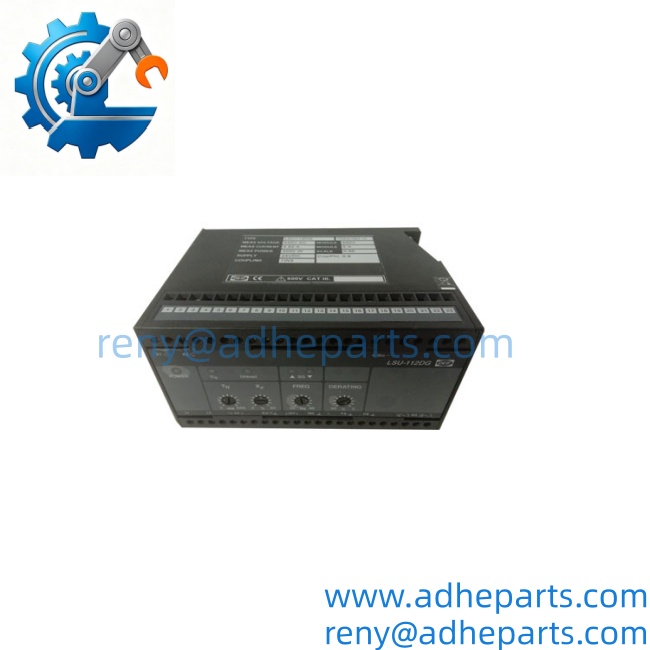
DEIF LSU-112DG
3. Key Technical Specifications
| Parameter | Value |
|---|---|
| Function | Frequency and active power control / load sharing |
| Application | Diesel and gas generator sets |
| Built-in Transducers | Power (I × cos φ) and frequency |
| Operating Modes | Stand-alone (frequency), parallel to grid (power), multi-generator load share |
| Speed Control Outputs | 2 relay contacts (raise/lower) |
| External Interfaces | Reference input 0–5 V, unload contact, optional external power/frequency transducers |
| Frequency Range | 40–70 Hz |
| Mounting | 35 mm DIN-rail or base mounting |
| Weight (approx.) | 0.75 kg |
| Typical Companion | Electronic potentiometer EPN-110DN or EPQ-96 for electronic governors |
4. Product Introduction (Anti-Template)
When multiple generators must share active load proportionally while maintaining stable frequency, the LSU-112DG performs the control. One unit is installed per generator. It measures voltage and current, calculates power and frequency with its built-in transducers, and compares these values on common paralleling lines (PS and FS) with the other units in the plant.
The unit can run a generator in stand-alone frequency-control mode, hold constant power when paralleled to the grid, or share load isochronously with other generators. Speed correction is issued via two relay contacts that interface to a mechanical governor or, through a DEIF electronic potentiometer, to an electronic speed controller. LED indicators show status and active control.
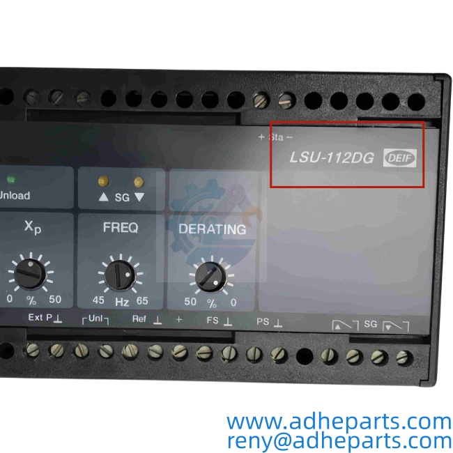
DEIF LSU-112DG
5. QC, Procurement & Logistics SOP
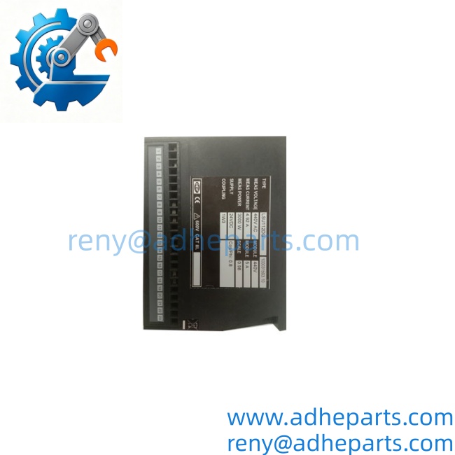
- Inbound Verification – Confirm full marking (LSU-112DG and 100031593.10 or equivalent), nameplate data (voltage/current ratings, coupling), terminal condition, and LED function. Photograph the label.
- Live Rig Testing – Apply auxiliary supply, inject calibrated voltage and current signals, verify power and frequency measurement accuracy, check raise/lower relay operation, and confirm paralleling-line behavior.
- QA & Anti-Static Packaging – After functional pass, protect terminals, clean the unit, and seal in anti-static or protective packaging with desiccant.
- Global Logistics & Export Compliance – Classify under the correct HS code for generator control relays. Packaging is rated for air and sea freight vibration; export documentation is prepared to minimize customs delays.
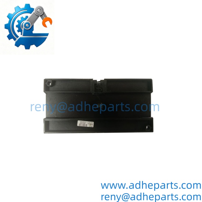
DEIF LSU-112DG
6. Technical Pitfalls & Integration Warnings
Measuring Circuit Matching – The unit must be ordered or calibrated for the correct secondary voltage, current, and power rating of the generator CTs/VTs. Mismatch produces incorrect load-share proportions.
Governor Interface – Direct connection is intended for mechanical governors. Electronic governors require a compatible DEIF electronic potentiometer (EPN-110DN or EPQ-96); incorrect interfacing prevents stable control.
Paralleling Line Wiring – All LSU-112DG units in a plant must share the common PS (power) and FS (frequency) lines correctly. Open or shorted paralleling lines cause unequal load sharing or frequency instability.
Unload Function – Activating the unload input forces the unit to ramp its generator to zero power. Incorrect use during parallel operation can cause reverse-power conditions on other sets.
DEIF LSU-112DG
7. Frequently Asked Questions (FAQ)
What is the realistic global lead time for a verified LSU-112DG?
Stock units typically ship within 1–5 business days after verification. Air freight adds standard transit time.
What is the main function of the LSU-112DG?
Active load sharing and frequency/power control of diesel or gas generators in stand-alone or parallel operation.
Does it have built-in transducers?
Yes. It includes both a power transducer (I × cos φ principle) and a frequency transducer.
How does it control the engine speed?
Via two relay contacts (raise and lower) that act on the governor. An electronic potentiometer is required for most electronic governors.
What mounting options are available?
35 mm DIN-rail or base/screw mounting.
Can it be used for reactive load sharing?
No. The LSU-112DG handles active power (kW) and frequency. Reactive (kVAr) sharing requires the LSU-122DG variant.
What does the number 100031593.10 represent?
It is a specific DEIF item/variant/order number for a configured unit.
Pre: Triconex 5600633 T8800 | Genuine OEM ICS Triplex T8800 Safety Control Module
Next: ABB 3ASC25H214 DATX130 | DCS Interface Module, In Stock