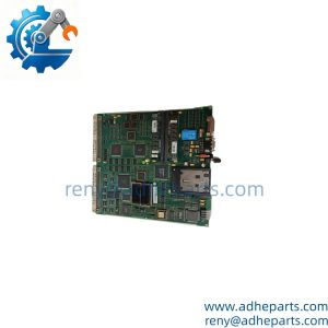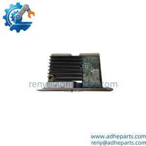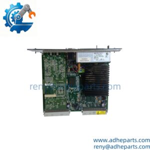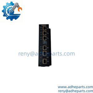
Description
Note: Many products are not yet listed. Please contact us for more product information. Our supply channels are constantly expanding, and we currently have 20 stable shared supply channels. Please confirm the model, product, price, and all other necessary information with customer service before placing an order. We offer new, refurbished, and used products, and prices are adjusted according to the year of the item you require.
Product Introduction
A feeder protection relay must do more than detect an overcurrent condition. It needs to coordinate breaker operation, distinguish fault conditions, and provide usable event information when maintenance teams investigate an unexpected trip. The GE Multilin F650 addresses these requirements through a combined protection, control, metering, and automation platform for distribution feeders and electrical substations.
Within an F650 installation, the relay can provide phase and ground overcurrent protection, voltage and frequency supervision, breaker failure logic, synchronism check, and automatic reclosing. Its programmable logic also supports customized interlocking and load-shedding schemes (particularly useful where multiple feeders or bus sections must operate together).
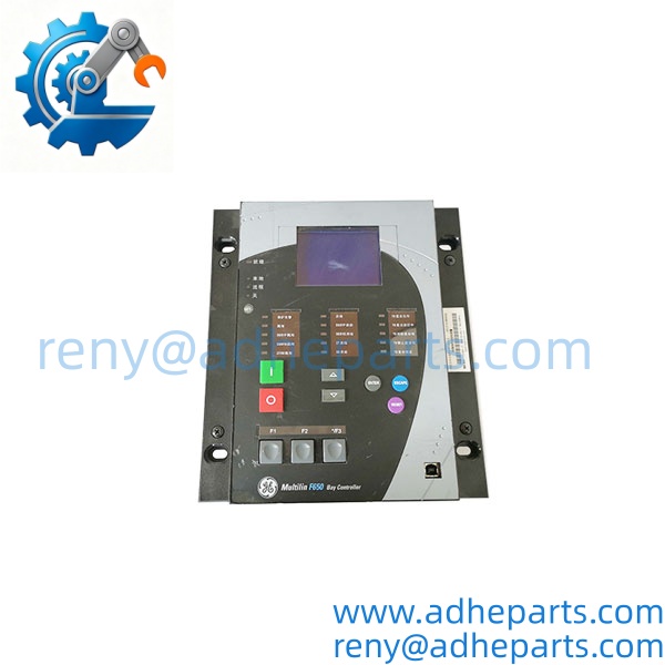
F650-B-F-G-F-2-G-1-HI-E
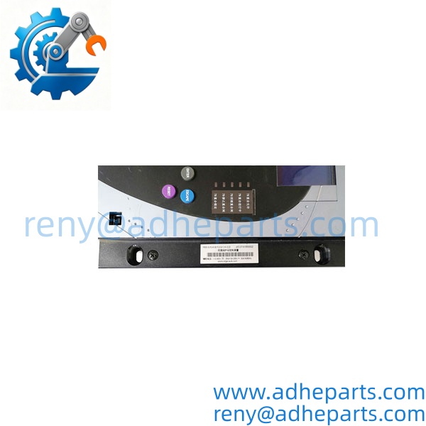
F650-B-F-G-F-2-G-1-HI-E
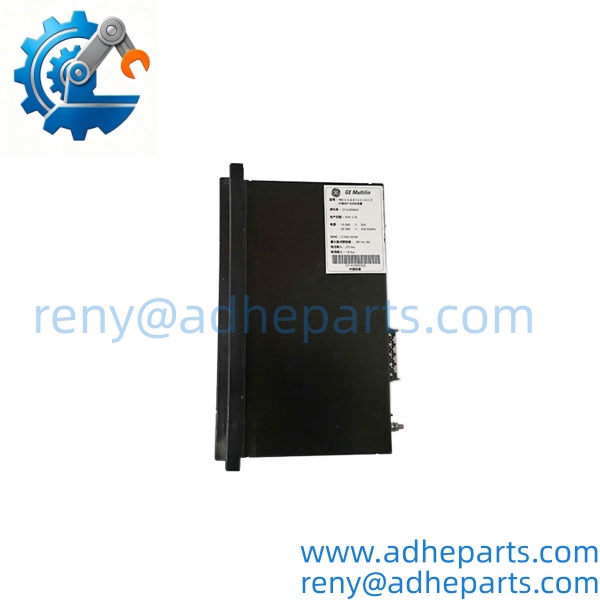
F650-B-F-G-F-2-G-1-HI-E
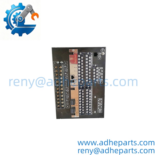
F650-B-F-G-F-2-G-1-HI-E
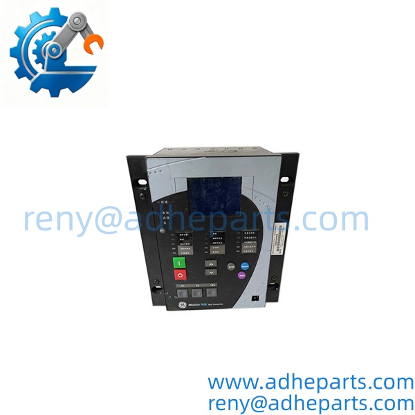
F650-B-F-G-F-2-G-1-HI-E
Key Technical Specifications
| Parameter | Specification |
|---|---|
| Manufacturer | GE Multilin |
| Product Family | F650 |
| Full Order Code | F650-B-F-G-F-2-G-1-HI-E |
| Device Type | Feeder Protection and Bay Controller |
| Auxiliary Supply | HI: 110–250 VDC / 120–230 VAC |
| DC Operating Range | 88–300 VDC |
| AC Operating Range | 96–250 VAC |
| Nominal Power Consumption | 25 VA |
| Maximum Power Consumption | 45 VA |
| Current Inputs | Suitable for 1 A or 5 A CT secondary circuits |
| Voltage Measurement Range | 2–275 VAC |
| Protection Functions | Phase, neutral, ground and sensitive ground overcurrent; voltage and frequency protection |
| Control Functions | Breaker control, breaker failure, synchronism check and autoreclosing |
| Communication Options | Ethernet and serial interfaces; protocol support depends on hardware configuration |
| Event Recording | Up to 479 time-tagged events |
| Oscillography | Up to 20 records |
| Installation | Half-width 19-inch rack, six-unit-high package |
| Operating Temperature | -20°C to +60°C |
Configuration note: The F650 platform supports multiple communication, I/O, and display arrangements. The complete order code and hardware revision must be checked before treating any interface or option as confirmed.
Field Application & Technical Pitfalls
Typical Applications
1. Medium-Voltage Distribution Feeders
The F650 can serve as the primary protection and control device for distribution feeders. Its overcurrent elements help detect phase and ground faults, while configurable time-current characteristics support coordination with upstream and downstream protection devices.
2. Substation Bay and Circuit Breaker Control
Breaker trip/close control, breaker failure protection, trip circuit supervision, and synchronism check make the suitable for bay-level control arrangements. It can also support bus transfer and interlocking schemes through programmable logic.
3. Industrial Power Distribution and Load Management
Voltage and frequency protection functions can support load-shedding strategies. In industrial plants with multiple incoming supplies or interconnected bus sections, this can help reduce the risk of a wider power interruption.
Three Replacement Pitfalls to Avoid
Pitfall 1: Matching only the family name
Two relays may have different rear communication boards, I/O cards, and auxiliary power configurations. A relay with the same base model is not automatically a drop-in replacement.
Pitfall 2: Overlooking the auxiliary supply
The HI supply option is designed for a different voltage range from the LO option. Confirm the actual DC battery or AC control supply available in the panel before installation.
Pitfall 3: Ignoring protection settings and logic
A replacement relay may require restoration of protection settings, programmable logic, breaker assignments, communication parameters, and I/O mapping. Installing the hardware without validating these settings can create serious commissioning problems.
Field lesson: Consider a feeder relay replacement after an unexplained breaker trip. The replacement unit powers up normally, but its digital input mapping differs from the original. The breaker status indication then becomes unreliable, even though the relay itself appears healthy. This is why a complete configuration and logic review matters just as much as checking the part number.
Quality Control (QC) SOP & Transparency
For GE procurement, our inspection process focuses on hardware identity and configuration accuracy.
- Nameplate Verification: Check the complete -B-F-G-F-2-G-1-HI-E order code, serial number, and available revision information.
- Hardware Inspection: Examine the front panel, display, casing, rear terminals, communication connectors, and I/O card positions.
- Power Supply Verification: Confirm the HI auxiliary supply designation and inspect the power input section for visible damage.
- Functional Testing: Where the appropriate test setup is available, power up the relay and check display operation, input/output response, communication interfaces, and selected protection functions.
- Configuration Review: Compare the available hardware arrangement with the requested I/O and communication configuration. Firmware and setting compatibility should be reviewed before commissioning.
- Final Inspection and Packing: Record the inspection findings, photograph the unit, and use suitable protective packaging for international transportation.
Live video inspection can be arranged after the unit arrives at our facility, subject to the inspection setup and availability.
Frequently Asked Questions
Q1: What is the GE Multilin used for?
It is a digital feeder protection and bay controller used in electrical distribution systems. Its functions include overcurrent protection, breaker control, electrical metering, event recording, and automation.
Q2: Is -B-F-G-F-2-G-1-HI-E a PLC module?
No. It is a dedicated protection relay and bay controller. Although it includes programmable logic and communication functions, it is not a general-purpose PLC CPU.
Q3: What auxiliary voltage does the HI version support?
The HI supply range is 110–250 VDC, with an operating range of 88–300 VDC, or 120–230 VAC, with an operating range of 96–250 VAC. Always check the actual nameplate before energizing the unit.
Q4: Does this model support Ethernet communication?
The specified configuration is listed with an Ethernet communication option. However, the exact port arrangement and supported protocols should be confirmed against the rear communication board and hardware revision.
Q5: Can I replace another model with this unit?
Not without checking the full order code. Display, communication hardware, I/O boards, power supply, and firmware can differ between configurations.
Q6: Does the support automatic reclosing?
Yes. The platform supports up to four reclosing attempts before lockout, subject to the configured protection scheme and application settings.
Q7: What warranty is available?
A 12-month warranty can be provided, subject to order confirmation and the agreed product condition. Inspection photographs and available test records can be supplied during the procurement process.