Description
Note: Many products are not yet listed. Please contact us for more product information. Our supply channels are constantly expanding, and we currently have 20 stable shared supply channels. Please confirm the model, product, price, and all other necessary information with customer service before placing an order. We offer new, refurbished, and used products, and prices are adjusted according to the year of the item you require.
3. Key Technical Specifications
Confirm each line against the OEM datasheet and the label on your existing unit before ordering. The PQM series was built in several configurations, and the T20-C suffix defines the display and communication options for this specific unit.
| Parameter | Value |
|---|---|
| Model | PQM-T20-C |
| Brand | GE Multilin |
| Product Family | PQM Power Quality Meter |
| Measurement Inputs | 3-phase voltage (V1, V2, V3) and 3-phase current (I1, I2, I3) plus neutral — verify on your unit |
| Voltage Input Range | Verify with OEM datasheet — typically 0–600V AC phase-to-phase |
| Current Input Rating | 5A or 1A CT secondary — verify on the unit label |
| Frequency | 45–65 Hz |
| Measurement Parameters | Voltage, current, real/reactive/apparent power, power factor, energy (kWh, kVARh), frequency |
| Harmonics Analysis | Up to 63rd order — verify firmware capability |
| Power Quality Events | Sag/swell, interruption, transient capture — verify firmware |
| Waveform Capture | Yes — verify sample rate and memory depth |
| Data Logging | Yes — verify memory capacity and logging intervals |
| Display | 20-character alphanumeric display — verify on your build |
| Communication Ports | Modbus RTU (RS-485) — verify port count and protocol options |
| Optional Communication | Ethernet or other protocols — verify on your specific unit |
| Digital Inputs | Verify count and function (e.g., status, demand sync) |
| Digital Outputs | Verify count and function (e.g., alarm, energy pulse) |
| Analog Outputs | Verify — some builds include 4–20mA outputs |
| Power Supply | 90–300V DC / 70–265V AC — verify range on the unit label |
| Power Consumption | Verify with OEM datasheet |
| Isolation | Verify — input to output to ground |
| Operating Temperature | –20 °C to +60 °C (typical — verify) |
| Storage Temperature | –40 °C to +85 °C (typical — verify) |
| Humidity | 5% – 95% RH, non-condensing |
| Mounting | Panel mount — verify cutout dimensions |
| Weight | Verify with OEM datasheet |
| Certifications | UL, CSA, CE — verify on the specific unit’s label |
4. Product Introduction
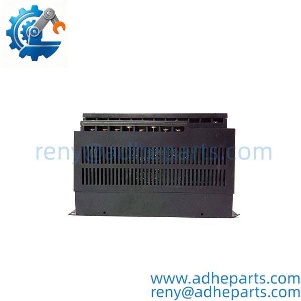
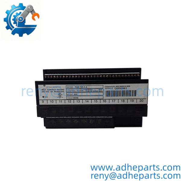
The GE PQM-T20-C is a panel-mount power quality meter from the Multilin PQM series. It measures voltage, current, power, energy, power factor, and frequency on a three-phase system, and it analyzes harmonics up to the 63rd order. It also captures power quality events — sags, swells, interruptions, and transients — and logs the data for later analysis. The 20-character display gives the operator a local readout without a separate HMI.
The engineering value is the combination of metering and power quality analysis in one panel-mounted device. A standard power meter tells you how much energy you are using. The PQM-T20-C tells you whether the power is clean — whether the harmonics are within limits, whether the voltage is sagging, and whether a transient is damaging your equipment. In my experience, that is the difference between knowing your energy bill and knowing why your drives keep tripping.
Two things decide whether a swap works. First, the CT ratio. The current readings depend on the CT primary and secondary ratings, and the meter must be configured to match the installed CTs. Second, the communication configuration. The Modbus address and baud rate must match the plant network. Record both from the old unit before you remove it.
PQM-T20-C
PQM-T20-C
5. Application Scenarios & Field Experience
Part 1 – Narrative Paragraph
The failure that hurts most on a power quality meter is not a dead display — it is a meter that reads normal while the power is actually dirty. The voltage looks fine on the average, but the harmonics are through the roof, and the drives on the line are overheating. I have seen that on a plant where the capacitor bank had failed and the harmonic distortion had climbed to 15% THD. The standard meter showed nominal voltage. The PQM-T20-C would have shown the harmonic spectrum and flagged the problem before the drives failed. When you replace a PQM, verify the CT ratio and the voltage configuration before you trust the readings.
Part 2 – Numbered List (Application Scenarios)
- Industrial Plants – Power Quality Monitoring – The meter is installed on the main incoming feeder to monitor voltage sags, harmonics, and power factor. The data helps the plant identify the source of equipment trips and avoid utility penalties.
- Data Centers – UPS and Distribution Monitoring – Used to monitor the power quality on the critical bus. The waveform capture and event logging help diagnose transient disturbances that cause server resets.
- Water Treatment – Pump Station Power Monitoring – The meter tracks energy consumption and power factor at a pump station. The digital outputs can signal a power quality alarm to the SCADA system.
- Manufacturing – Drive Line Power Analysis – Installed on a feeder that supplies variable frequency drives. The harmonic analysis identifies resonance conditions and helps size harmonic filters correctly.
Part 3 – Short Field Story
A bottling plant had a line of VFD-driven conveyors that would trip on overcurrent every few hours. The maintenance team had replaced the drives and the motors, and the trips continued. We installed a PQM-T20-C on the feeder and logged the power quality for a week. The log showed voltage notches and harmonic distortion that correlated with the trips. The root cause was a failing capacitor bank on the same bus. The plant repaired the capacitor bank, and the trips stopped. The PQM- had shown the problem that the standard meters could not see.
6. Standard Operating Procedure (SOP) for Quality Control
- Visual & Origin Inspection – We verify the GE Multilin marking, model string, and the date code. We inspect the display for cracks or dead segments and the terminals for damage. A unit with a damaged display or evidence of moisture ingress is rejected.
- Revision and Firmware Documentation – We read and photograph the full model string, the firmware revision, and the configuration settings where accessible. That record ships with the unit so you can compare it against the unit you are replacing.
- Power-Up Self-Test – The meter is powered at rated voltage. We verify it completes its boot sequence and that the display shows normal operation.
- Voltage and Current Input Verification – We apply calibrated voltage and current signals to the inputs and verify the meter’s readings against the reference. Accuracy must stay within the OEM specification.
- Harmonics Verification – We inject a known harmonic signal and verify the meter reports the correct harmonic magnitude and phase.
- Communication Test – We connect to the Modbus port and verify the meter responds to queries. We record the protocol settings so you can compare them against your plant’s setup.
- Digital I/O Verification – We exercise each digital input and output and verify the meter responds correctly.
- ESD-Safe Packaging – The meter is wrapped in anti-static film, seated in a foam insert with the terminals protected, and packed in a double-wall carton with static warning labels.
7. Frequently Asked Questions (FAQ)
Q1: What is the difference between and other PQM models?
A: The PQM series includes several models with different display sizes, communication options, and I/O counts. The T20 in the model number typically indicates a 20-character display, and the C suffix denotes a specific communication or feature configuration. I cannot confirm the exact build from the base number alone. Read the full model string on your existing unit and match it exactly before you order. If you send us a photo of the label, we will confirm the match.
Q2: Will this meter work with my existing CTs?
A: The meter supports 5A or 1A CT secondary inputs, and the specific rating is marked on the unit label. You must also configure the meter for the CT primary and secondary ratings in your installation. If the CT ratio does not match the meter configuration, the current and power readings will be incorrect. Verify the CT rating on your existing unit and the CTs in your panel before ordering.
Q3: What is the warranty on this meter?
A: We offer a 12-month warranty from the ship date. It covers display failure, measurement input failure, communication port failure, and power supply failure under normal operating conditions. It does not cover damage from incorrect voltage or current input, reversed CT polarity, or physical damage to the display. We test every meter on a calibrated bench before it ships.
Q4: Do you have this exact model in stock?
A: PQM inventory moves and varies by build. Confirm availability before you plan an outage. If we are out of the variant, we will tell you what we actually have and whether a different build would suit your application. Do not assume any PQM will configure the same way.
Q5: Any installation pitfalls I should watch for?
A: Four. First, verify the CT ratio and the voltage configuration before you power up — incorrect settings will produce wrong readings and may damage the meter. Second, check the CT polarity and the voltage phase sequence; a reversed CT or a swapped phase will cause negative power readings. Third, record the Modbus address and baud rate from the old unit before you remove it. Fourth, after the swap, verify the readings against a known reference and check the communication with the SCADA system before you return the circuit to service. A meter that powers up is not necessarily measuring correctly.