Description
Note: Many products are not yet listed. Please contact us for more product information. Our supply channels are constantly expanding, and we currently have 20 stable shared supply channels. Please confirm the model, product, price, and all other necessary information with customer service before placing an order. We offer new, refurbished, and used products, and prices are adjusted according to the year of the item you require.
Key Technical Specifications
| Parameter | Value |
|---|---|
| Manufacturer | MOOG |
| Model Number | G123-825-001 |
| Product Type | DIN Buffer Amplifier |
| Supply Voltage | 24 VDC nominal (22–28 VDC) |
| Current Consumption | 65 mA (no output load); 170 mA (100 mA output) |
| Voltage Input | 0 to ±10 VDC |
| Current Input | 4–20 mA; 0 to ±100 mA |
| Voltage Output | 0 to ±10 VDC, minimum load 1 kΩ |
| Current Output | 4–20 mA, maximum load 500 Ω; selectable 0 to ±5/10/20/30/50 mA |
| Maximum Valve Drive Current | ±100 mA |
| Input Filter | Single-pole active filter |
| Filter Frequency | 7, 16, 34, 72, and 723 Hz (±10%) |
| Mounting | DIN Rail |
| Protection Rating | IP20 |
| Operating Temperature | 0 to 40°C (32 to 104°F) |
| Dimensions | 100 × 108 × 22.5 mm (W × H × D) |
| Weight | Approximately 120 g |
Source: MOOG G123-825-001 official technical datasheet. Specifications should be checked against the applicable hardware revision and installation requirements.
moog.com+1
Product Introduction
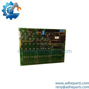
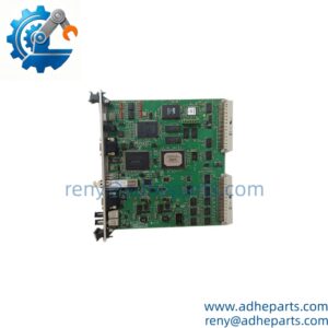
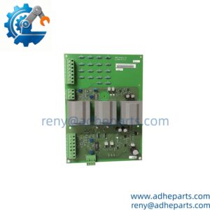
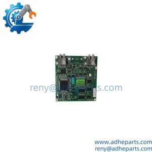
The MOOG G123-825-001 is a DIN rail-mounted buffer amplifier designed to interface PLC or servo amplifier outputs with Moog servo and proportional valves. It accepts ±10 V, 4–20 mA, and mechanical feedback current signals, converting them into selectable voltage or current outputs required by the valve.
Its switch-selectable output ranges and five input filter frequencies allow engineers to match different valve drive requirements. It also supports the integration of electrical feedback valves into certain existing systems using mechanical feedback servo amplifiers, subject to application compatibility.
moog.com+1
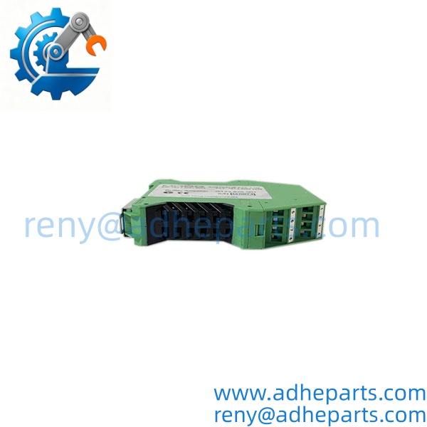
G123-825-001
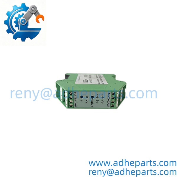
G123-825-001
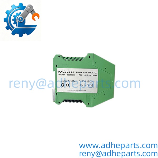
G123-825-001
Application Scenarios & Field Experience
Part 1 – Engineering Challenges
A common problem in hydraulic servo systems is the mismatch between controller output signals and valve input requirements. A PLC may provide a ±10 V analog command or a 4–20 mA signal, while the connected Moog valve requires a different voltage or current range.
The G123-825-001 addresses this interface problem. It conditions and converts analog signals between the controller and valve, while its selectable input filter helps reduce electrical noise that can affect valve command signals. It also provides an interface option for certain MFB-to-EFB valve replacement projects without requiring replacement of the existing servo amplifier.
moog.com+1
Part 2 – Typical Application Scenarios
1. Steel Manufacturing – Hydraulic Rolling Mill Control
- Process: Hydraulic roll gap adjustment and servo valve positioning.
- Requirement: Converts controller analog commands into the voltage or current signals required by the hydraulic valve.
2. Power Generation – Steam Turbine Hydraulic Control
- Process: Hydraulic actuator and valve positioning systems.
- Requirement: Provides signal conditioning between the control electronics and compatible servo valve assemblies.
3. Industrial Machinery – Injection Molding Equipment
- Process: Hydraulic pressure, flow, and actuator control.
- Requirement: Matches PLC analog outputs to proportional valve command requirements.
4. Heavy Industry – Hydraulic Press Systems
- Process: Press movement, force regulation, and hydraulic positioning.
- Requirement: Provides selectable current or voltage outputs for compatible hydraulic valve applications.
Part 3 – Illustrative Field Case
A hydraulic equipment operator experienced unstable valve response after replacing an older mechanical feedback valve with an electrical feedback version. The existing servo amplifier produced a signal that did not directly match the replacement valve’s input requirements. Engineers introduced a compatible G123-825-001 buffer amplifier, configured the output range, and adjusted the input filter. After verifying the command signal and valve response, the system was returned to operation.
Illustrative engineering scenario based on the documented application principles of the product; not a verified customer installation.
Standard Operating Procedure (SOP) for Quality Control
Our QC process for the MOOG G123-825-001 focuses on product identification, electrical condition, signal configuration, and packaging protection.
1. Visual & Origin Inspection
- Verify the MOOG manufacturer identification and part number.
- Inspect the housing, terminal connections, PCB, and mounting structure.
- Check available OEM labels, packaging, and identification markings.
- Inspect for corrosion, physical damage, burned components, or signs of unauthorized repair.
- Record the actual product condition before shipment.
2. Live Rig Testing
- Verify the required 24 VDC supply before powering the unit.
- Check the internal supply status indicator (Vs).
- Inspect the voltage and current output indicators (Vv and Iv).
- Where a suitable test setup is available, verify ±10 V and 4–20 mA signal conversion.
- Check selectable current output settings and filter operation.
- Verify terminal connections and output behavior under appropriate test loads.
3. Firmware & Configuration Verification
- This is an analog buffer amplifier, not a programmable PLC or digital controller.
- No conventional firmware revision verification is applicable.
- Record hardware identification and inspect the S1/S2 configuration switches.
- Verify the input signal selection, output current range, and filter frequency settings against the intended application.
- Document any configuration differences before shipment.
4. ESD-Safe Packaging
- Handle electronic assemblies using ESD-protected procedures.
- Place the unit in anti-static packaging.
- Protect terminal connections and the housing against impact.
- Use suitable moisture-resistant outer packaging.
- Verify the model number and shipping label before dispatch.
5. Pre-Shipment Confirmation
- Provide actual product photographs upon request.
- Arrange live video inspection before shipment.
- Confirm condition, quantity, and warranty terms.
- Provide shipping documentation and tracking information after dispatch.
Frequently Asked Questions (FAQ)
Q1: Can the MOOG replace an existing servo amplifier or work with different Moog valve models?
A: The is a buffer amplifier, not a standalone servo amplifier. It interfaces between an existing PLC or servo amplifier and compatible Moog servo/proportional valves. Its selectable voltage and current outputs provide flexibility, but compatibility must be checked against the specific valve’s electrical requirements, including input impedance, rated current, and feedback type.
Q2: What warranty do you provide for the MOOG ?
A: We offer a 12-month warranty, subject to confirmed order terms. The warranty covers qualifying product-related failures under normal operating conditions. Physical damage, incorrect wiring, and unauthorized modifications are excluded.
Q3: Is the MOOG available from stock, and how quickly can you ship it?
A: Availability and condition are subject to actual stock confirmation. We can provide product photographs and arrange a live video inspection before shipment. For confirmed available stock, our standard shipping arrangement is generally within one week after payment.
Q4: Does the require firmware matching?
A: No conventional firmware matching is required because this is an analog signal-conditioning device. However, configuration matching is essential. Check the S1 and S2 switch positions, input signal type, output current selection, and filter frequency. An incorrect setting can produce an unsuitable valve command signal.
Q5: What should engineers check before installing the ?
A: Pay particular attention to the following:
- Confirm the supply voltage is within 22–28 VDC.
- Check the polarity and wiring of all analog signal connections.
- Verify the input type: ±10 V, 4–20 mA, or MFB current signal.
- Set the correct valve output voltage or current range.
- Check the selected filter frequency against the application requirements.
- Verify the output load does not exceed the specified limits.
- Ensure proper cable shielding and grounding.
Important: The is designed for DIN rail mounting and has an IP20 protection rating. Install it inside a suitable electrical enclosure. Do not change signal selection switches or disconnect valve wiring while the system is operating unless the approved maintenance procedure specifically permits it. Incorrect output settings can cause unexpected valve movement or hydraulic system instability.