Description
Note: Many products are not yet listed. Please contact us for more product information. Our supply channels are constantly expanding, and we currently have 20 stable shared supply channels. Please confirm the model, product, price, and all other necessary information with customer service before placing an order. We offer new, refurbished, and used products, and prices are adjusted according to the year of the item you require.
Product Introduction
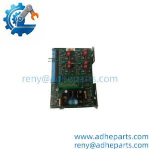
When catalytic bead combustible‑gas monitoring loses channel processing, plant safety systems cannot trigger alarms for flammable vapor buildup. This plug‑in rack‑mount card delivers sensor excitation, performs gas‑level computation, and drives local alarm indicators within the System 57 subrack chassis.
Well, technically it works only paired with catalytic‑type detector heads; 4‑20 mA transmitters require the sibling 05701‑A‑0301 hardware, —though your mileage may vary depending on field cable resistance and overall loop length.
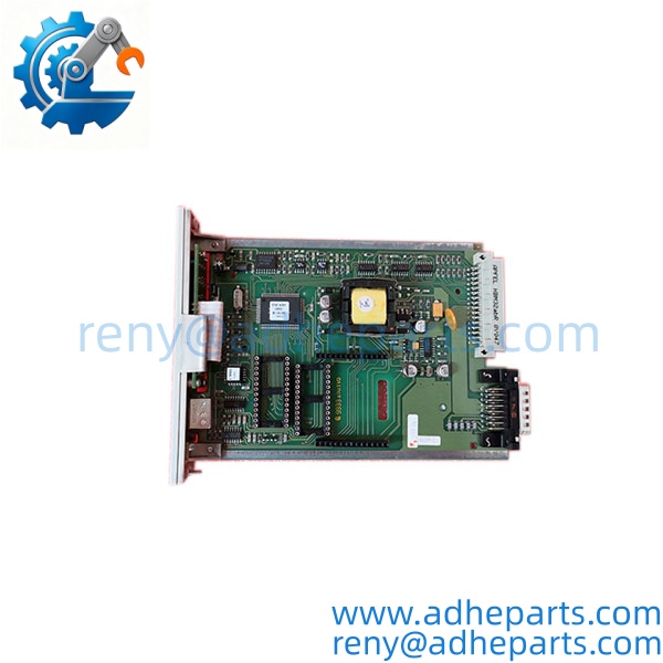
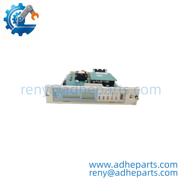
05701-A-0302
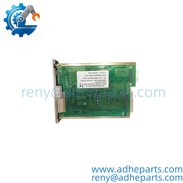
05701-A-0302
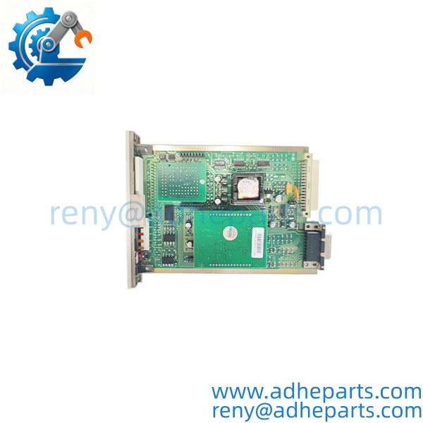
05701-A-0302
Key Technical Specifications
| Parameter | Value |
|---|---|
| Host Rack | Honeywell System 57 3U 19‑inch subrack |
| Supported Sensor | Catalytic bead combustible gas detector |
| Supply Voltage | 18 VDC to 32 VDC nominal DC input |
| Typical Power Draw | 3.75 W (includes connected catalytic sensor) |
| Local Indicators | A1/A2/A3 alarm LEDs, Fault LED, Inhibit LED |
| Front‑panel Interface | Push‑button reset / channel select, 25‑segment analog bargraph display |
| Output Options | Configurable alarm relays, optional plug‑in 4‑20 mA analog output module |
| Remote Inputs | Inhibit, Reset (active‑high / active‑low configurable) |
| Operating Ambient Temp | 0 °C to +60 °C |
| Humidity | 5 %‑95 % non‑condensing |
| Diagnostic Functions | Open‑loop, short‑circuit, sensor fault detectionManualsLib |
Field Application & Technical Pitfalls (The Engineer’s Guide)
Critical Industrial Scenarios
- Refinery process units: provides continuous point‑monitoring of hydrocarbon vapor for process area safety and ESD interlock logic.
- Petrochemical compressor houses: tracks combustible gas buildup around seal assemblies and pressurized piping runs.
- Off‑site tank farm installations: fits System 57 rack hardware for perimeter gas detection without full DCS point expansion.
Technical Pitfalls (Bold Warnings)
- Mismatch between control‑card type and field sensor hardware: Installing this catalytic‑only card onto 4‑20 mA transmitters yields permanent channel‑fault states, no valid gas readings will populate the bargraph. Always cross‑reference detector type before card swap‑out.
- Excessive field wiring resistance across long detector runs: High loop resistance distorts catalytic bead excitation voltage, producing drifting readings that mimic real gas concentration spikes. Measure resistance across the third terminal block from the card front for loop validation.
- ESD damage during hot card extraction inside live rack: Even though cards can be pulled from powered racks, unprotected handling can corrupt channel calibration memory without immediate visible fault codes. Wear grounded wrist straps during maintenance.
Lesson‑Learned Anecdote One refinery maintenance crew swapped a spare 05701‑A‑0302 card during a short turnaround window. They reused existing wiring originally wired for 4‑20 mA transmitters and skipped sensor‑type verification. For three operational days the channel stayed locked in fault status. Operators wrote it off as a bad detector, until technicians traced the root cause: wrong control‑card variant fitted for the installed field hardware.
Quality Control (QC) SOP & Transparency
- Inbound Verification: Cross‑check part number and serial number against OEM nameplate; visual anti‑counterfeit inspection for resoldered front‑panel LED connections or aftermarket printed labels; store nameplate photograph in internal inventory records.
- Live Rig Testing: Insert card inside working System 57 test subrack; apply 24 VDC rack supply; run power‑on self‑test; verify all LED alarm and fault indicator states; simulate catalytic‑sensor input to validate bargraph deflection and relay‑trigger thresholds.
- Parameter Testing: Measure input power draw under simulated full‑scale gas condition; validate remote inhibit / reset input trigger levels; confirm no false fault flags across multiple test cycles.
- Final QA & Packaging: Clean edge‑connector contacts with static‑safe cleaner; seat unit inside conductive anti‑static bag; apply QC‑passed sticker stamped with test completion date; place inside rigid shock‑absorbent shipping container.
Frequently Asked Questions (FAQ)
Can I remove or insert 05701‑A‑0302 while the System 57 rack remains powered? Physical hot‑removal is mechanically allowed, yet not risk‑free. Unprotected hot‑swap raises ESD‑related memory‑corruption risk. Isolate the channel via remote inhibit before card extraction whenever site workflow permits.
Can this card work with standard 4‑20 mA gas transmitters? No. This unit is built exclusively for catalytic bead sensors. For 4‑20 mA detector heads you need model 05701‑A‑0301. Verify exact sensor model with the OEM datasheet before ordering replacement hardware.
What warranty terms apply to stocked Honeywell 05701‑A‑0302 units? All supplied units carry a 12‑month warranty. New‑surplus hardware covers factory‑origin defects. Refurbished units cover faults linked to our test workflow; field‑side surge, wiring faults or sensor‑caused damage sit outside warranty coverage.
How can I tell genuine OEM hardware from rebuilt counterfeit copies? Genuine Honeywell cards carry crisp silkscreen printing, original front‑panel membrane overlay, and intact factory serial labels. Rebuilt units often show rework solder around terminal pins or blurry adhesive‑applied replacement serial stickers.
My replacement card shows constant channel‑fault alarm right after rack insertion. Is the unit defective? Do not conclude hardware failure immediately. Confirm you have matched card type to field‑installed catalytic sensor, check field wiring for open‑circuit or short‑circuit conditions, and inspect terminal‑block screw torque. Most persistent faults stem from field‑side issues.
Does 05701‑A‑0302 include the analog output module? No. The 4‑20 mA isolated analog output is an optional plug‑in accessory sold separately. It is not factory‑populated onto the base control‑card assembly.
What cabinet environmental limits must I observe for reliable long‑term service? Keep rack ambient temperature within 0 °C to +60 °C and maintain non‑condensing humidity. Sustained high cabinet temperature accelerates aging of on‑board electrolytic capacitors and shortens expected service life of this safety‑critical card.