Description
Note: Many products are not yet listed. Please contact us for more product information. Our supply channels are constantly expanding, and we currently have 20 stable shared supply channels. Please confirm the model, product, price, and all other necessary information with customer service before placing an order. We offer new, refurbished, and used products, and prices are adjusted according to the year of the item you require.
Product Introduction
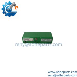
The 1794‑TB3 is a widely deployed terminal base within the modular FLEX I/O distributed system. It physically hosts plug‑in I/O modules, terminates field wiring, and passes digital backplane communication across the Flexbus inter‑base connector. This base supports 3‑wire sensor wiring topologies including separate signal, common, and field‑supply connections for both discrete and many analog 1794 modulesRockwell A….
As a mature active‑production component, it remains heavily used for brown‑field plant expansions and spare‑part stock. While the base itself rarely suffers electronic failure, mechanical damage to Flexbus mating pins, loose screw terminals, and mis‑applied torque are the leading root causes of intermittent I/O faults in the field. This base is not functionally interchangeable with spring‑clamp TB3S or low‑voltage TB32 variants; mis‑matching terminal bases creates field‑power routing failures and persistent adapter fault bits.
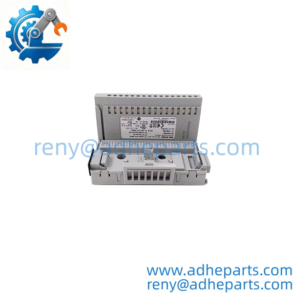
1794‑TB3
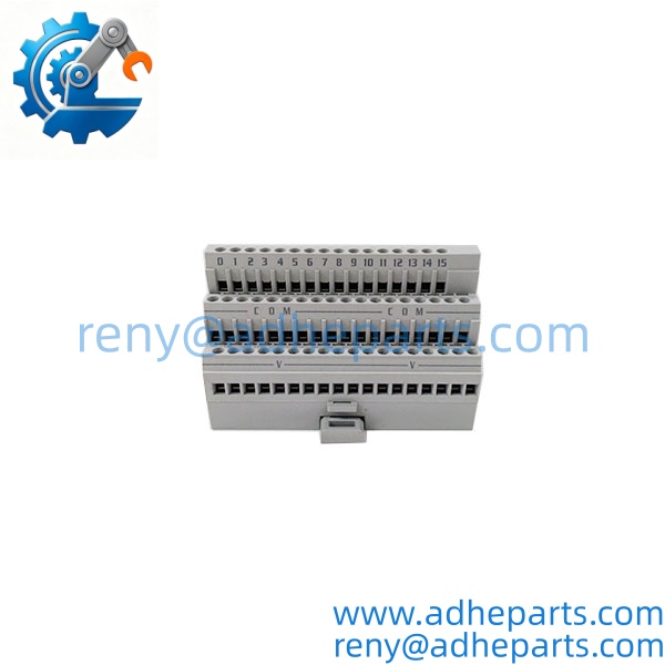
1794‑TB3
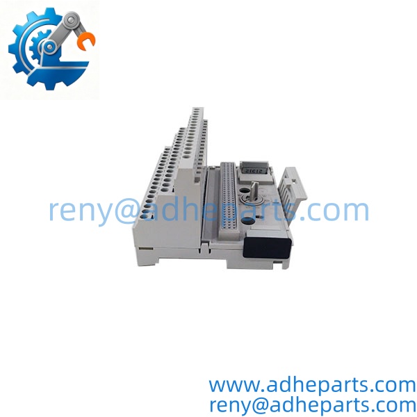
1794‑TB3
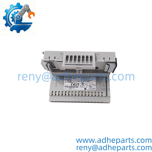
1794‑TB3
Key Technical Specifications
| Parameter | Value |
|---|---|
| System Compatibility | 1794 FLEX I/O modules (compatible discrete / analog cards) |
| Termination Style | Cage‑clamp screw‑type, three‑wire signal layout |
| Total Terminals | 52 terminals:16 I/O points,18 COM,18 +V supply terminals |
| Continuous Field Voltage Rating | 125 V AC / 125 V DC; max transient 132 V AC |
| Max Common‑Strip Current | 10 A aggregate |
| Flexbus Backplane Draw | 640 mA @5 VDC |
| Recommended Wire Gauge | 22‑12 AWG (0.34‑3.3 mm²), solid / stranded copper |
| Terminal Screw Torque | 0.56‑0.79 N·m (5‑7 lb‑in) |
| Mounting | 35 mm DIN‑rail or direct panel mounting |
| Operating Ambient Temperature | ‑20 °C … +70 °C (‑4 °F … 158 °F) |
| Storage Temperature | ‑40 °C … +85 °C |
| Relative Humidity | 5‑95 % non‑condensing |
| Certifications | UL 508, CSA C22.2, Class I Division 2 Groups A‑D, CE |
| Vibration / Shock | 5 G @10‑500 Hz vibration; 30 G operating shock |
| Dimensions (module fitted) | 94 × 94 × 69 mm (3.7 × 3.7 × 2.7 in) |
| Weight | 0.28 kg |
| Lifecycle Status | Active‑mature, factory build available |
Field Application & Technical Pitfalls (The Engineer’s Guide)
Critical Industrial Scenarios
- Distributed remote I/O racks on manufacturing production lines, placing FLEX I/O near sensors and actuators to shorten expensive field‑signal cable runs back to main PLC cabinets.
- Water‑wastewater pumping stations: remote I/O enclosures handling level‑transmitter analog signals plus discrete valve and pump feedback / control wiring.
- Refinery and chemical plant Class I Div 2 classified zones: remote FLEX nodes interfacing process instruments where cabinet space near controllers is limited.
Technical Pitfalls (Bold Warnings)
- ⚠️ Flexbus pin mechanical damage: Forcing adjacent terminal bases together bends or fractures the plastic‑housing female Flexbus connector. Damaged pins produce random intermittent I/O drop‑outs, adapter communication time‑outs, and slot‑identification faults with no obvious burn or smoke signs. Never jam bases together; align and slide gently when assembling DIN‑rail stacks.
- ⚠️ Incorrect screw‑torque application: Under‑torqued cage‑clamp terminals creep loose under thermal cycling and vibration, creating high‑resistance intermittent connections. Over‑torque fractures screw heads or deforms cage‑clamp metal hardware. Strictly adhere to 5‑7 lb‑in torque value; stranded wire strands escaping terminal blocks risk phase‑to‑short faults inside the enclosure.
- ⚠️ High‑vibration mounting without rail locks: On vertically‑mounted DIN‑rails or locations with heavy machinery vibration, un‑locked terminal bases can creep apart along the rail, breaking Flexbus interconnection. Use 1492‑EA35 DIN‑rail locking clips for high‑vibration environmentsManualsLib.
- ⚠️ Base‑module incompatibility: Certain high‑density analog modules (example 1794‑IE12) require specialized TB3G terminal bases. Installing them on standard 1794‑TB3 leads to stuck FieldPowerOff fault bits and missing channel power, even with correct field‑side wiring. Always cross‑reference module datasheet for required terminal‑base catalog number before assembly.
- ⚠️ Debris ingress during installation: Metal shavings, stray wire strands falling into base housing during wiring work can cause latent short‑circuit events after power‑up. Keep protective covers in‑place while drilling cabinet mounting holes; clear all conductive debris before applying power.
Real‑world field anecdote: A packaging‑plant controls crew expanded a FLEX remote I/O rack during scheduled downtime. Technicians forced two adjacent 1794‑TB3 bases together without careful alignment. Power‑up completed with no immediate errors, but over three weeks of production, random slots would drop offline intermittently. Troubleshooting swapped I/O modules, adapter, and field wiring with zero improvement. Physical inspection revealed bent Flexbus female pins on one terminal base; replacing the damaged TB3 fully eliminated the intermittent communication failures.
Quality Control (QC) SOP & Transparency
- Inbound Verification: Confirm catalog number, series revision, OEM label integrity. Full visual inspection: examine Flexbus female connector pins for bending, cracking or broken plastic housing. Inspect each cage‑clamp screw; check for stripped threads, tool damage or burn discoloration on terminal metal contacts. Reject units with cracked plastic bodies.
- Mechanical Fit‑Test: Physically mate a known‑good 1794 I/O module into the base, verify positive latching lock‑in action, no binding or play. Daisy‑chain stack multiple terminal bases to validate smooth Flexbus inter‑base sliding engagement without forcing.
- Continuity & Resistance Check: Multimeter test continuity across common‑strip and supply‑strip internal bus paths. Confirm no unintended short‑circuits between isolated signal groups and Flexbus backplane contacts. Cycle every terminal screw through open‑close operation to confirm cage‑clamp mechanical function.
- Final QA & Packaging: Fit plastic transport protective cover over Flexbus mating connector. Place unit inside static‑shield bag. Apply internal QC‑passed sticker noting test date and inspector ID. Package in rigid shock‑absorbent transit carton.
Frequently Asked Questions (FAQ)
Can I hot‑swap just the I/O module while leaving 1794‑TB3 base powered and mounted on DIN‑rail? Yes. The FLEX I/O design supports module hot‑swap; terminal base stays powered and mounted. Always follow hazardous‑area work practices: do not perform hot‑swap in classified locations unless area is proven non‑hazardous.
What is the difference between 1794‑TB3 and 1794‑TB3S? 1794‑TB3 uses cage‑clamp screw terminals. 1794‑TB3S is the spring‑clamp tool‑actuated variant. They are mechanically interchangeable on DIN‑rail but terminal hardware differs; cannot mix‑match for same physical wiring harness.
Will 1794‑TB3 work with 1794‑IE12 analog input module? Functional limitations apply. 1794‑IE12 requires 1794‑TB3G terminal base for correct field‑power distribution. Deploying on TB3 results in FieldPower‑Off fault state, channels will not operate properly. Always validate module‑base pairing in OEM installation manual.
What warranty coverage applies for new‑surplus / refurbished 1794‑TB3? Twelve‑month standard warranty applies. Exclusions include mechanical damage from forced assembly, bent Flexbus pins, over‑torqued / stripped screw terminals, field‑wiring short‑circuit damage, and vibration‑induced movement without DIN‑rail locks.
Is the terminal base itself a repairable component after Flexbus connector pins get bent? No. Damaged Flexbus connector on the base unit cannot be reliably repaired; full replacement of 1794‑TB3 is required. Attempts to manually bend deformed pins back in place create latent intermittent‑fault risk.
Can I mix different terminal‑base types within one Flexbus rack stack? Mechanically they will mount together, yet mixing TB3, TB32, TB3G variants in same rack is strongly discouraged unless every slot’s module datasheet explicitly approves that specific base. Mismatched power‑distribution traces inside different base models introduce hard‑to‑diagnose I/O faults.
今天 10:01
Allen-Bradley 1794-TB3的详细参数
Allen-Bradley 1794-TB3的应用场景有哪些?
提供一些关于Allen-Bradley 1794-TB3的用户评价