Description
Note: Many products are not yet listed. Please contact us for more product information. Our supply channels are constantly expanding, and we currently have 20 stable shared supply channels. Please confirm the model, product, price, and all other necessary information with customer service before placing an order. We offer new, refurbished, and used products, and prices are adjusted according to the year of the item you require.
3. Key Technical Specifications
Do not order against this table alone. I cannot confirm the module type, channel count, or electrical ratings from the part numbers. The three numbers provided likely represent a single assembly or a matched set (module, base, connector). Match every line against the OEM datasheet and the labels on your existing hardware.
| Parameter | Value |
|---|---|
| Primary Model | SDK-C0148 |
| Associated Part Numbers | 12003-101-01 (module or base) / SBS05M09B (connector or sub‑assembly) — verify relationship |
| Brand | ALSTOM |
| Product Family | Verify — confirm the host system or rack |
| Module Type | Verify — confirm whether this is a control card, an interface module, or a connector assembly |
| Compatible System | Verify — confirm the rack, chassis, or panel |
| Number of Channels | Verify with OEM datasheet |
| Input / Output Signal Type | Verify with OEM datasheet |
| Signal Range | Verify with OEM datasheet |
| Isolation | Verify — field side to logic side |
| Power Supply | Verify — voltage rail and current draw |
| Connector Type | Verify — confirm the SBS05M09B connector type and pinout |
| Status Indicators | Verify — LED or flag arrangement varies by revision |
| Jumper / Switch Settings | Verify — record from your existing hardware before ordering |
| Operating Temperature | Verify for your panel ambient |
| Storage Temperature | –40 °C to +85 °C (typical — verify) |
| Humidity | 5% – 95% RH, non-condensing |
| Mounting | Verify — rack, panel, or DIN rail |
| Weight | Verify with OEM datasheet |
| Certifications | Verify on the specific unit’s label |
4. Product Introduction
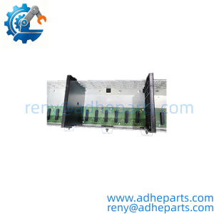
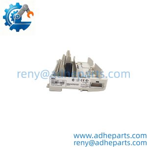
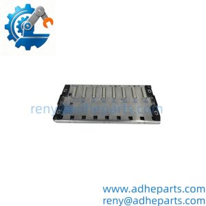
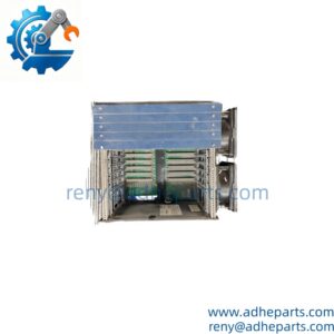
The ALSTOM SDK-C0148, together with part numbers 12003-101-01 and SBS05M09B, appears to form a control module or interface assembly for an Alstom legacy system. The three numbers likely represent the main board, a base or mounting element, and a connector or sub‑assembly. I cannot confirm the exact function or the system it serves from the numbers alone. I am not going to guess.
Here is what I can tell you as a straight answer: on legacy Alstom hardware, compatibility is system-specific and often assembly-specific. The three part numbers you provided must be matched as a set. A replacement module that carries the same base number but a different suffix or a different associated part number may not function correctly in your rack. Before you order, read the labels on all three components and cross‑reference them against the OEM documentation for your system. If you send me a photo of the labels and the rack they came out of, I will confirm what you are looking at.
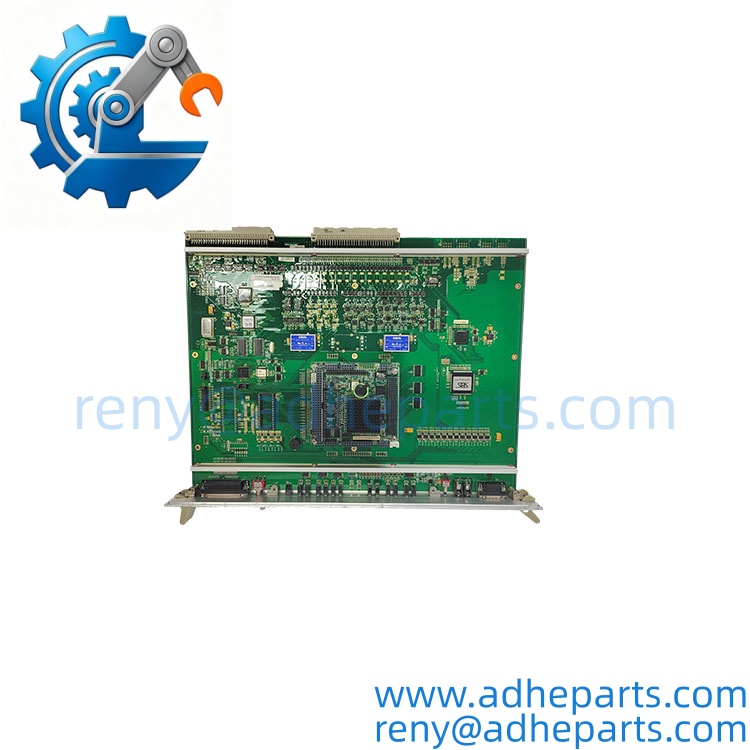
SDK-C0148
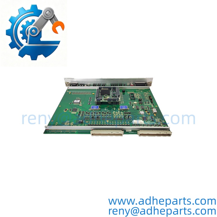
SDK-C0148
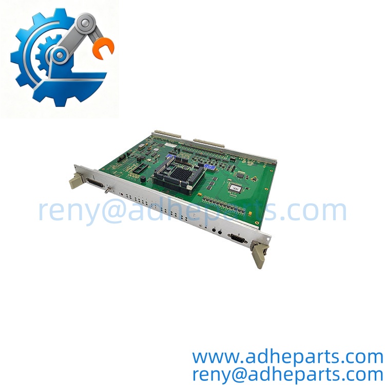
SDK-C0148
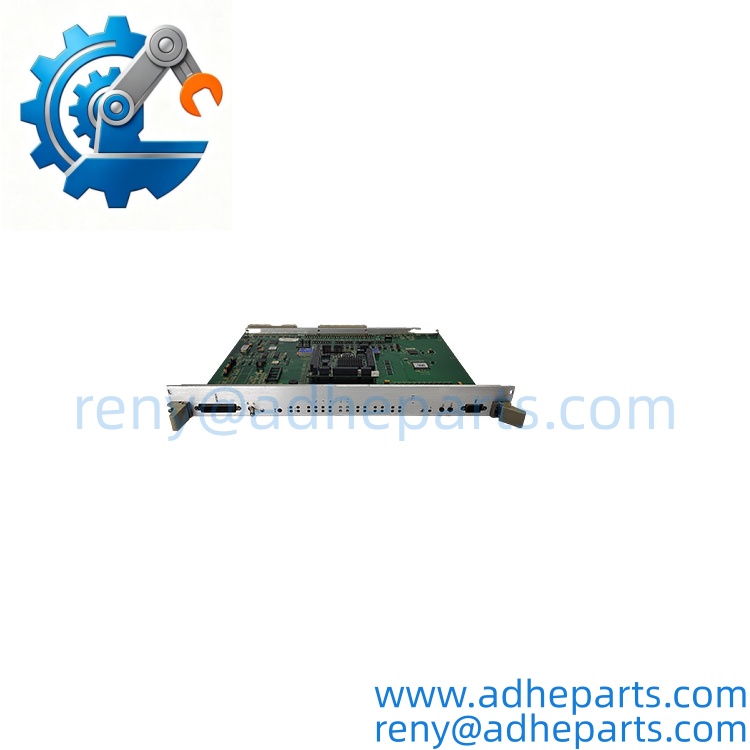
SDK-C0148
5. Application Scenarios & Field Experience
Part 1 – Narrative Paragraph
The failure that costs the most on a legacy Alstom assembly is a mismatched part number set that passes a bench check and still fails in the rack. I have seen a plant replace a module with the correct primary number but the wrong connector sub‑assembly, and the system would not initialize. The module was fine. The connector pinout was different. On Alstom hardware of this generation, the associated part numbers are not optional details — they define the physical and electrical interface. That is the rule that matters more than any single specification on the datasheet.
Part 2 – Numbered List (Application Scenarios)
- Power Generation – Legacy Control System Maintenance – The assembly is used in an Alstom control rack for turbine or boiler auxiliary monitoring. A mismatched part number set causes the controller to reject the module, and the operator loses visibility on the affected points.
- Oil & Gas – Compressor Station Control – Used to condition or communicate signals from field instruments. The assembly must match the rack’s input type and the field device’s signal range, or the data will be corrupted or scaled incorrectly.
- Water Treatment – Plant-Wide Instrumentation – The assembly interfaces transmitters or switchgear to the control system. A failed channel or connector shows up as a frozen value or a non‑responsive circuit on the operator station.
- Industrial Plants – Legacy Control Retrofit – Used where an Alstom control system is still in service and the OEM no longer stocks the exact variant. Replacement is often the only path short of a full controller migration.
Part 3 – Short Field Story
A power plant had a legacy Alstom control system on a boiler auxiliary that started logging intermittent “I/O fault” alarms. The crew had replaced the field transmitter and the cable. The fault kept coming back. We asked for the part numbers on the module and the connector. It turned out the replacement module had the correct SDK-C0148 number but the associated connector was a different sub‑assembly (SBS05M09B variant). The controller was rejecting the module under load, and the fault only appeared when the boiler was at high fire. We supplied the matching set, and the alarms stopped. The hardware had been fine — the part number set was wrong.
6. Standard Operating Procedure (SOP) for Quality Control
- Visual & Origin Inspection – We verify the Alstom marking, the SDK-C0148 model string, the 12003-101-01 and SBS05M09B numbers, and the date codes. We inspect connectors, terminals, and the housing for cracks, corrosion, or moisture ingress. A module with a damaged connector or evidence of rework is rejected.
- Part Number Set Documentation – We read and photograph all three part numbers, the revision suffixes, and any jumper or switch settings. That record ships with the assembly so you can compare it against the hardware you are replacing.
- Compatibility Cross‑Check – We verify the part number set against the OEM documentation for the system you specify. A module or connector that does not match the requested application is set aside rather than shipped.
- Power‑Up Self‑Test – The module is powered on a bench fixture at the specified rail voltage. We verify it initializes without a fault and that the status indicators show normal operation.
- Signal Path Verification – For interface modules, we apply a known input and measure the output against the OEM specification. Accuracy must stay within the datasheet limit.
- Connector Integrity Test – We mate and unmate the SBS05M09B connector ten times to confirm the contacts do not deform and the retention mechanism holds.
- Isolation Test – We apply the rated isolation voltage between circuits and between a circuit and ground. Leakage current must stay below the datasheet limit.
- ESD‑Safe Packaging – The assembly is wrapped in anti‑static film, seated in a conductive foam insert with the connectors protected, and packed in a double‑wall carton with static warning labels.
7. Frequently Asked Questions (FAQ)
Q1: Are these three part numbers a single assembly?
A: They likely form a matched set: the SDK-C0148 module, the 12003-101-01 base or mounting element, and the connector or sub‑assembly. I cannot confirm the exact relationship without the OEM documentation. Send us a photo of the labels and the rack they came out of, and we will confirm whether they belong together.
Q2: Is the connector interchangeable with other similar connectors?
A: Not necessarily. The connector part number defines the pinout and the physical keying. A different connector with the same physical size may not have the same pinout or may not mate correctly. Match the full part number, not just the family.
Q3: What is the warranty on this assembly?
A: We offer a 12‑month warranty from the ship date. It covers manufacturing defects under normal operating conditions. It does not cover damage from incorrect installation, mechanical impact, or operation beyond the rated range. For electrical components, the warranty is void if the part shows evidence of overvoltage or reversed polarity. Every assembly ships with a test report where applicable.
Q4: Do you actually have this in stock?
A: This is legacy inventory, and I will not pretend otherwise. Stock on Alstom assemblies of this class varies by part number set, and the exact combination you need may not be on the shelf. Confirm availability before you plan an outage. If we are out, we will tell you what we actually have rather than quote a date we cannot hold.
Q5: Any installation pitfalls I should watch for?
A: Four. First, power down the rack before inserting or removing the module — these modules are not hot‑swap capable. Second, record all three part numbers, the revision suffixes, and any jumper or switch settings from the old assembly before you remove it. Third, confirm the replacement set matches the module, the base, and the connector. Fourth, after the swap, verify the module is recognized by the controller and that the signal path is correct before you return the system to service. A module that powers up is not necessarily communicating correctly.