Description
Note: Many products are not yet listed. Please contact us for more product information. Our supply channels are constantly expanding, and we currently have 20 stable shared supply channels. Please confirm the model, product, price, and all other necessary information with customer service before placing an order. We offer new, refurbished, and used products, and prices are adjusted according to the year of the item you require.
3. Key Technical Specifications
Do not order against this table alone. I cannot confirm the exact channel count, resolution, and scan rate from the model number. Match every line against the OEM datasheet and the label on your existing board.
| Parameter | Value |
|---|---|
| Model | VMIVME-3122 |
| Brand | GE Fanuc (VMIC) |
| Product Family | VMIVME VMEbus I/O |
| Module Type | Analog input board |
| Form Factor | 6U double-height Eurocard |
| Channel Count | Verify — typical build is 64 single-ended or 32 differential; confirm on your board label |
| A/D Resolution | Verify — 16-bit class; confirm on your board label |
| Input Signal Ranges | Verify with OEM datasheet — confirm voltage and current ranges on your build |
| Scan / Throughput Rate | Verify with OEM datasheet |
| Input Impedance | Verify |
| VMEbus Interface | Slave interface, A16/A24, D8/D16/D32 — verify address space and data width |
| Field Connection | Verify — front-panel connector or P2 backplane; confirm on your build |
| Isolation | Verify — input to VMEbus side |
| Power Supply | From VMEbus backplane (+5V, +12V, -12V) — verify current draw |
| Power Consumption | Verify with OEM datasheet |
| Trigger / Timing | Verify — external trigger, scan start, and interrupt capability |
| Status Indicators | Verify — LED arrangement varies by revision |
| Jumper / Switch Settings | Verify — record from your existing board before ordering |
| Operating Temperature | 0 °C to +55 °C (typical — verify) |
| Storage Temperature | –40 °C to +85 °C (typical — verify) |
| Humidity | 5% – 95% RH, non-condensing |
| Weight | Verify with OEM datasheet |
| Certifications | CE, UL — verify on the specific unit’s label |
4. Product Introduction
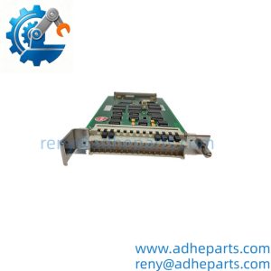
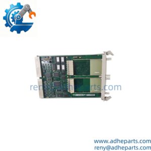
The GE VMIVME-3122 is a 6U VMEbus analog input board from the GE Fanuc / VMIC product line. It converts field analog signals into digital data that a VME host can read over the backplane. It is the board that brings analog measurement into a VME-based data acquisition or control system.
The engineering value is the channel density on a single VME slot. In a 6U chassis with a limited slot count, packing dozens of analog channels onto one board leaves slots free for the CPU and the communication cards. In my experience, the most common integration issue with this class of board is not the A/D conversion itself — it is the field wiring and the input configuration. A board set for differential inputs with single-ended wiring, or a range jumper in the wrong position, will produce readings that look like sensor failures. Read the jumper settings from your existing board before you order the replacement.
Two things decide whether a swap works. First, the input configuration. The channel mode, the range, and the field connection must match the replacement. Second, the VMEbus address and interrupt settings. The host software expects the board at a specific address, and a replacement with different DIP switch settings will not be recognized.
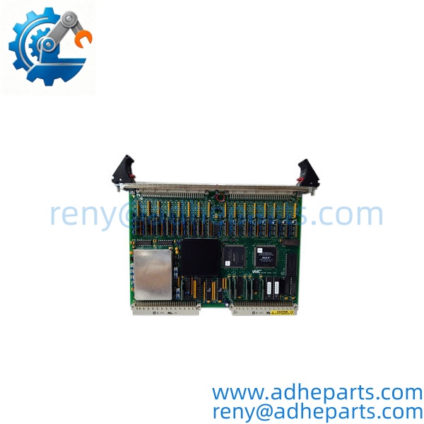
VMIVME-3122
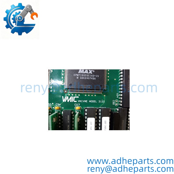
VMIVME-3122
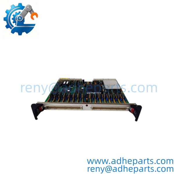
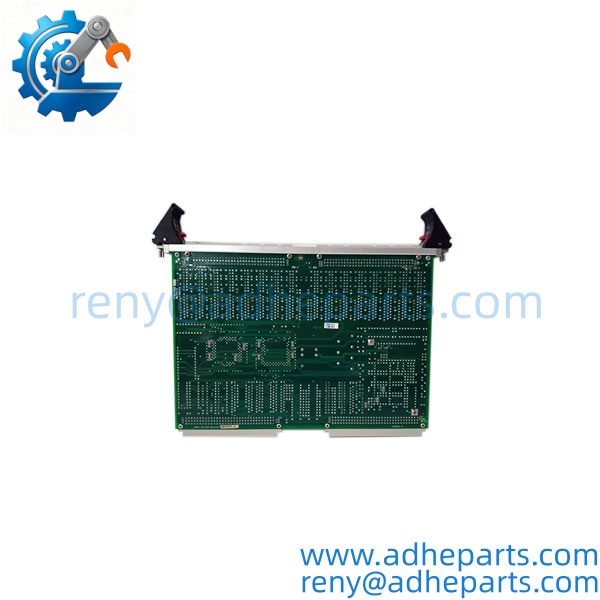
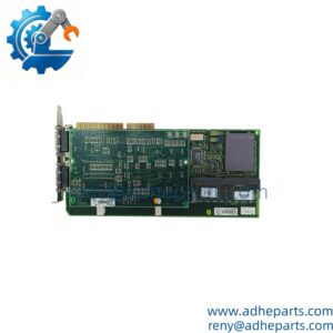
VMIVME-3122
5. Application Scenarios & Field Experience
Part 1 – Narrative Paragraph
The failure that hurts most on an analog input board is not a dead channel — it is a channel that reads within tolerance on a bench check and drifts under temperature. The board passes the self-test, the readings look reasonable, and the data acquisition system logs the values. What nobody sees is that the readings have drifted outside the specification because the front-end amplifier has aged. I have seen a test stand pass boards because the A/D was reading 0.2% low on the high range. The board was functionally alive. The accuracy was gone. When you buy a surplus VME analog board, ask for a test report that shows the measured accuracy across the range, not just a power-on check.
Part 2 – Numbered List (Application Scenarios)
- Test and Measurement – VME Data Acquisition – The board captures analog signals from strain gauges, pressure transducers, and thermocouples in a rack-mounted test system. The channel density lets one slot cover a full test article.
- Power Generation – Turbine Test Stand Instrumentation – Used in a VME-based test stand to acquire temperature, pressure, and flow signals during turbine testing. The board’s scan rate and channel count match the test’s sampling requirements.
- Aerospace – Structural Test Data Acquisition – The board samples load cells and displacement transducers during structural fatigue tests. The input isolation protects the VME host from the test article’s ground references.
- Industrial Control – Legacy VME Monitoring Systems – Used where a VME-based control system needs to monitor analog process signals. Replacement is often the only path when the OEM no longer stocks the board.
Part 3 – Short Field Story
A test facility had a VME-based data acquisition system that was passing test articles with marginal results. The test engineer suspected the analog input board and sent it to us for evaluation. We ran an accuracy check across the full input range and found the board was reading 0.15% low at the top of the range — outside the specification for the test’s tolerance. The board had been in service for over a decade and had never been recalibrated. We supplied a replacement with a current test report, the facility recalibrated the system, and the marginal test results stopped. The original board had been working — it was just out of specification.
6. Standard Operating Procedure (SOP) for Quality Control
- Visual & Origin Inspection – We verify the GE Fanuc / VMIC marking, the VMIVME-3122 model string, and the date code. We inspect the 96-pin DIN P1/P2 connectors for bent pins and the front-panel connector for damage. A board with a cracked connector or evidence of moisture ingress is rejected.
- Revision and Configuration Documentation – We read and photograph the full model string, the revision code, all jumper and switch settings, and the channel configuration. That record ships with the board so you can compare it against the unit you are replacing.
- VMEbus Fit Verification – Each board is seated in a powered 6U VME test chassis to confirm the connector engages fully and the retention mechanism holds. A board that fits loosely will cause intermittent backplane faults.
- Power-Up Self-Test – The board is powered in a live chassis and we verify it completes its boot sequence and that the host recognizes the board at the configured address.
- Input Channel Verification – We apply calibrated analog signals to each channel across the configured range and verify the board’s reported values against the reference. Accuracy must stay within the OEM specification. We test at multiple points to catch a drifted front-end amplifier.
- VMEbus Data Transfer Test – We run a continuous read loop from the host and verify the data is stable and free of bus errors. Zero errors over the test period is the pass criterion.
- Connector Integrity Test – We mate and unmate the backplane connector ten times to confirm the contacts do not deform and the retention mechanism holds.
- ESD-Safe Packaging – The board is wrapped in anti-static film, seated in a conductive foam insert with the edge connector protected by a rigid shroud, and packed in a double-wall carton with static warning labels.
7. Frequently Asked Questions (FAQ)
Q1: How many channels does the VMIVME-3122 have?
A: I cannot confirm the exact channel count from the model number alone. This board family was built in single-ended and differential configurations, and the channel count depends on the build. Read the label on your existing board and compare it to the replacement before you order. If you send us a photo of the board label, we will confirm the channel configuration.
Q2: What input ranges does the board support?
A: The input ranges are set by jumpers or configuration on the board, and the supported ranges depend on the build. Verify the ranges against the OEM datasheet and the jumper settings on your existing board. A replacement with different range jumpers will produce incorrect readings until the settings are matched.
Q3: What is the warranty on this board?
A: We offer a 12-month warranty from the ship date. It covers component failure, channel failure, VMEbus interface failure, and connector failure under normal operating conditions. It does not cover damage from overvoltage on the inputs, ESD damage from handling without a wrist strap, or physical damage to the connectors. We test every board in a live VME chassis with calibrated inputs before it ships.
Q4: Do you have this exact board in stock?
A: VMIVME inventory is legacy and varies by revision. Confirm availability before you plan an outage. If we are out of the variant you need, we will tell you what we actually have rather than quote a date we cannot hold.
Q5: Any installation pitfalls I should watch for?
A: Four. First, power down the VME chassis before inserting or removing the board — these boards are not hot-swap capable. Second, record the jumper and switch settings from the old board before you remove it, including the channel mode, the input range, and the VMEbus address. Third, verify the field wiring matches the channel configuration; a differential board wired single-ended will read incorrectly. Fourth, after the swap, inject a known signal into each channel and verify the host reports the correct value before you return the system to service. A board that powers up is not necessarily measuring accurately.