Description
Note: Many products are not yet listed. Please contact us for more product information. Our supply channels are constantly expanding, and we currently have 20 stable shared supply channels. Please confirm the model, product, price, and all other necessary information with customer service before placing an order. We offer new, refurbished, and used products, and prices are adjusted according to the year of the item you require.
Key Technical Specifications
| Parameter | Value |
|---|
| Catalog Number | 2364-SPM03A |
| OEM | Rockwell Automation (Allen-Bradley) |
| Functional Identity | RGU main control printed circuit board |
| Monitored Channels | 3 × current transformers (3-phase current monitoring) |
| Board Assembly | 192638, Rev 01 (per multiple listings — verify against your unit) |
| Documented Version | 3.01 (distributor record) |
| Net Weight | 2.45 lb (~1.11 kg) |
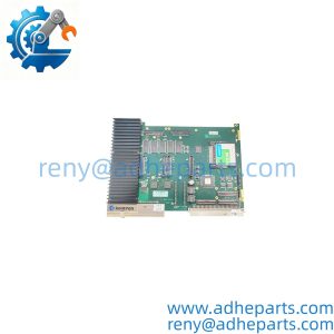
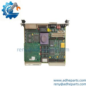
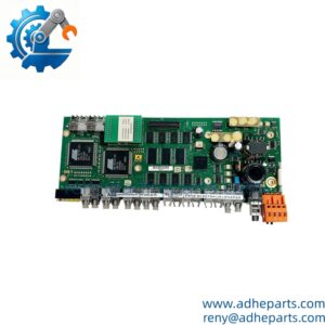
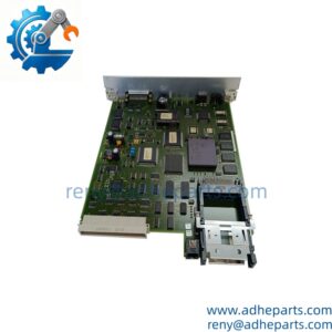
| Form Factor | PCB with on-board connectors and thermal hardware (per unit photographs) |
| Protocol / Interface Detail | Not published in a verifiable source — confirm from your RGU system documentation |
| Operating Environment | Electronics-cabinet mounting inside the RGU assembly |
| Lifecycle Status | Legacy; sustained through secondary-market spares |
Honest note on this table: beyond the identity, CT channel count, weight, and board assembly number, we found no verifiable electrical specifications from an OEM manual. Values such as 24 V DC, 5 A, and various I/O counts appearing on secondary listings contradict each other and appear invented — treat any spec sheet that does not trace back to Rockwell documentation with suspicion. Confirm supply voltage, interface pinout, and configuration method against your existing unit and system manual before purchase.
Product Introduction
The Allen-Bradley 2364-SPM03A is the main control board inside Rockwell Automation’s RGU assembly — the printed circuit board that manages three-channel CT current monitoring for the unit. It is the intelligence of the gateway: sampling the current transformers, running the monitoring logic, and serving the data onward to the host system.
Its engineering value is straightforward: when an RGU loses current measurement or communication, this board is the component-level repair that restores the unit without replacing the entire assembly. For sites still running these gateways in power or motor-monitoring service, a tested spare board on the shelf converts a weeks-long procurement problem into an afternoon swap.
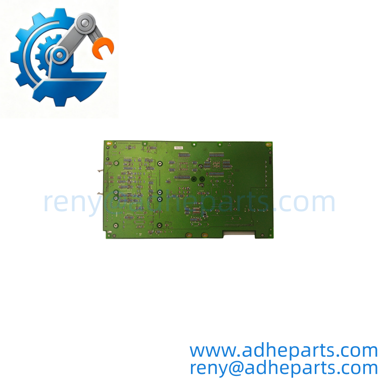
2364-SPM03A
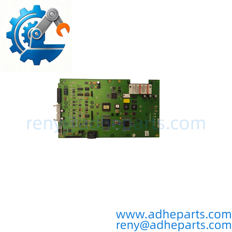
2364-SPM03A
Application Scenarios & Field Experience
Part 1 — The Engineering Pain Point
Current-monitoring gateways fail quietly. The process keeps running, but the power data feeding your energy management or protection logic freezes — and the first sign is often a historian gap or a missed demand peak, not an alarm. Because the RGU is a packaged assembly, many plants default to replacing the whole unit at packaged-unit prices. The 2364-SPM03A board is the component-level alternative: diagnose the board, swap the board, keep the enclosure, wiring, and configuration.
Part 2 — Specific Application Scenarios
- Industrial Power Monitoring — Feeder current acquisition: The RGU’s three CT channels track phase currents on a feeder or motor circuit; a failed 2364-SPM03A blanks that telemetry until the board is replaced.
- Motor Control Lineup — Load trending and protection supervision: Plants trending motor load for maintenance planning depend on the gateway’s current data; the control board keeps that data path alive.
- Energy Management — Demand and consumption reporting: The gateway feeds consumption data to the plant energy system; a board-level repair restores reporting without re-commissioning the metering chain.
- Component-Level Repair Depot — Board exchange stock: Shops that maintain RGU assemblies keep tested 2364-SPM03A boards as rotating spares, cutting repair turnaround from procurement lead time to bench time.
Part 3 — Field Story
A plant’s motor-feeder monitoring went dark on three circuits served by one gateway — operators noticed only when a weekly load report showed flatlined current on a running 200 HP motor. The gateway enclosure checked out; power was good, but the control board had failed. The electrician pulled a tested 2364-SPM03A spare from the bench stock, transferred it into the enclosure, and current telemetry returned after a configuration check. The failed board went out for component-level analysis; the site added a second spare board to the depot the same week.
Standard Operating Procedure (SOP) for Quality Control
Every 2364- board we ship passes this four-stage process:
- Visual & Origin Inspection
- Board-level verification first: assembly number (192638) and revision read from the PCB silkscreen, photographs provided to the buyer before dispatch — mandatory for this part number given the volume of fabricated listings around it
- Solder joint, connector, and thermal hardware inspection under magnification
- Component date-code consistency check; signs of rework or prior field repair documented
- Live Bench Testing
- Board powered on the appropriate bench supply with current-limited protection
- On-board power rails verified at test points; processor/clock activity confirmed
- CT channel inputs exercised with a calibrated current source; channel scaling verified against known reference values where the bench fixture allows
- Firmware / Configuration Verification
- On-board firmware or version identifier (documented distributor record: 3.01) read and recorded on the test certificate
- Any stored configuration dumped and archived so it can be restored to match your site settings
- ESD-Safe Packaging
- Board sealed in anti-static bag with desiccant and humidity indicator
- Foam-cushioned, double-boxed, with QC certificate, board photographs, and revision record enclosed
Frequently Asked Questions (FAQ)
Q1: How do I know the 2364- is the board I need for my RGU? A: Match three things before ordering: the catalog number on the board label, the assembly number (192638) and revision in the silkscreen, and the connector layout against your failed board. Photographs settle this in minutes — we send them proactively. Be aware that searching this part number returns fabricated descriptions (PLC, drive board, I/O module, safety relay); those listings describe different hardware entirely, and their “specifications” do not apply.If your failed board is not an RGU control board, this is not your part.
Q2: What warranty do you offer? A: 12 months from shipment on new surplus and refurbished boards. Board-level failures are often intermittent — a cracked joint or degrading rail that passes a quick power-on check — so our bench test exercises all three CT channels with a current source under load, not just a visual check. Failures inside the warranty window are repaired or replaced at our cost.
Q3: Is it in stock, and how fast does it ship? A: Legacy board supply is finite and availability moves quickly. We confirm physical stock and send board photographs against your order before quoting a ship date; typical dispatch is 1–3 business days from confirmed stock, with expedited handling for line-down situations. If your site operates multiple RGU units, we recommend holding one tested spare per few gateways — these boards will not get easier to source.
Q4: Will a replacement board work immediately after installation? A: Physically, if assembly number, revision, and connectors match, the board drops into the enclosure. Functionally, plan for a configuration verification pass: confirm firmware version (documented record: 3.01) and restore your site’s channel scaling, CT ratios, and communication settings from your archived configuration. Boards pulled from other sites or from unknown e-waste streams may arrive with settings that do not match your installation — a five-minute check beats a day of mystery telemetry.
Q5: What are the installation pitfalls? A: Three rules from the bench. First, work ESD-safe and fully de-energize the RGU — the assembly monitors live CT circuits, so confirm the monitored circuit is isolated before opening the enclosure. Second, photograph every connector position before removal; these boards use multi-pin headers where a single mis-aligned plug reads as a dead channel, not a wiring fault. Third, verify CT channel mapping after the swap with a known load — a swapped channel pair corrupts your phase reporting silently, and energy dashboards will quietly disagree with the switchgear meters until someone cross-checks.