Description
Note: Many products are not yet listed. Please contact us for more product information. Our supply channels are constantly expanding, and we currently have 20 stable shared supply channels. Please confirm the model, product, price, and all other necessary information with customer service before placing an order. We offer new, refurbished, and used products, and prices are adjusted according to the year of the item you require.
3. Key Technical Specifications
The order-code suffix defines the build. Confirm each line against the label on your existing relay and the OEM datasheet for your system. The P1 code means 1A CT inputs; do not substitute a P5 (5A) unit without checking the CTs.
| Parameter | Value |
|---|---|
| Model | 469-P1-HI-A20-E |
| Brand | GE Multilin |
| Product Family | 469 Motor Management Relay |
| CT Input Rating (P1) | 1A nominal — verify CT secondary rating in your switchgear |
| CT Input Burden | Verify with OEM datasheet — confirm on the relay label |
| Frequency | 45 – 66 Hz |
| Protection Elements | Thermal overload, short circuit, ground fault, phase unbalance, under/overvoltage, under/overfrequency, jam, stall, locked rotor, starts-per-hour |
| Measurement Accuracy | Current ±0.5% of reading, voltage ±0.5% of reading — verify at 25 °C |
| Relay Outputs | Enhanced I/O package (A20) — verify exact count and contact rating on the unit label |
| Digital Inputs | Enhanced I/O package (A20) — verify exact count and voltage range on the unit label |
| Analog Outputs | Verify count and signal range on the unit label — A20 package |
| RTD Inputs | High-insulation (HI) RTD circuits — verify count and supported RTD types on the unit label |
| Communication Ports | RS-485 (Modbus RTU), front RS-232, Ethernet (E) — verify supported protocols and firmware revision |
| Display | 16-character x 4-line backlit LCD — verify on your build |
| Event Recorder | 256 time-stamped events — verify firmware capacity |
| Power Supply | 90 – 300V DC / 70 – 265V AC — verify range on the unit label |
| Operating Temperature | –40 °C to +60 °C — display may become sluggish below –20 °C |
| Certifications | UL 508, CSA C22.2, CE, IEC 60255 — verify on the specific unit’s label |
4. Product Introduction
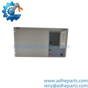
The GE Multilin 469-P1-HI-A20-E is a motor management relay for medium-voltage and large low-voltage induction motors. It combines thermal overload protection, short-circuit protection, ground fault detection, and motor-thermal modeling in one panel-mounted unit. The order code tells you what this build carries: P1 for 1A CT inputs, HI for high-insulation RTD circuits, A20 for the enhanced I/O package, and E for Ethernet communication.
The technical edge is the adaptive thermal model. The relay calculates winding temperature from a bi-thermal model and resets the thermal capacity used based on the motor’s cooling rate during stops. That matters on high-inertia loads where a simple overload curve trips too early or too late. The HI RTD circuits add dielectric margin for motors above 3 kV, and the event recorder gives you a time-stamped sequence when a trip happens.
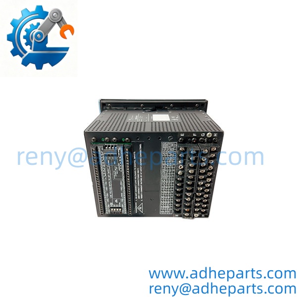
469-P1-HI-A20-E
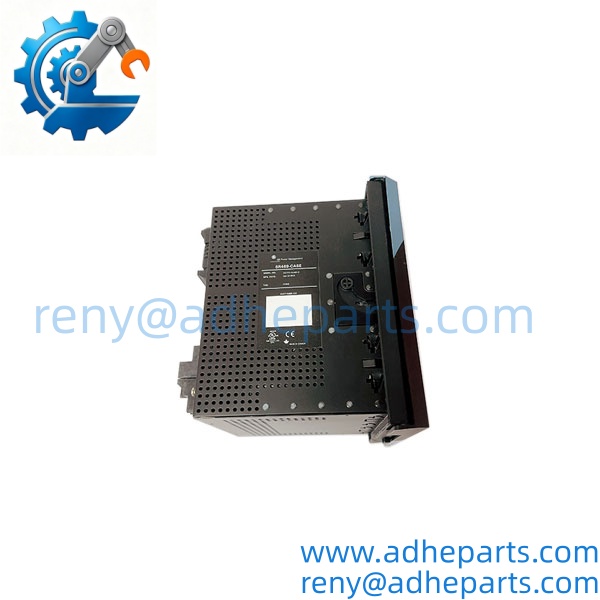
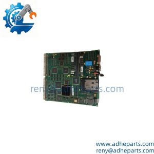
469-P1-HI-A20-E
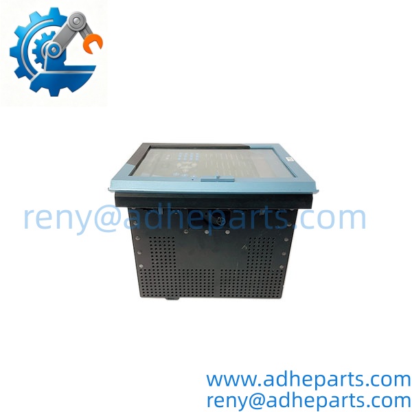
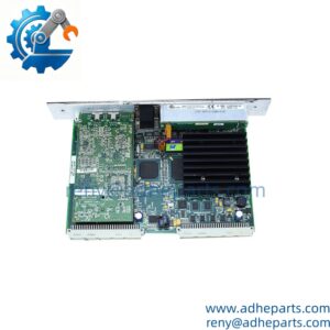
469-P1-HI-A20-E
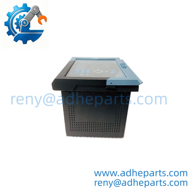
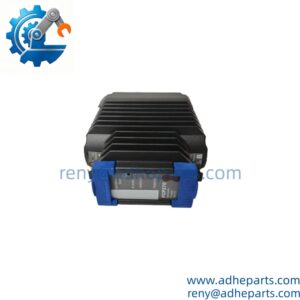
469-P1-HI-A20-E
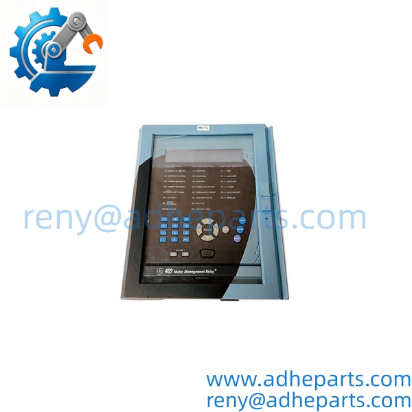
469-P1-HI-A20-E
5. Application Scenarios & Field Experience
Part 1 – Narrative Paragraph
The problem this relay solves is the trip you cannot explain. A 1,000 HP fan motor trips on “overload,” the ammeters show normal current, and the crew replaces the motor. The real cause is often a phase imbalance from a failing contactor or a single-phase voltage sag. The 469 catches that with its negative-sequence current element and its voltage inputs, and the event recorder shows the sequence: which phase dropped, when, and for how long. In my experience, that record is the difference between a guessing game and a repair order that fixes the actual problem.
Part 2 – Numbered List (Application Scenarios)
- Power Generation – Forced Draft Fan Motors – The 469 protects large FD and ID fan motors with long start times. The thermal model accounts for the acceleration period, and the RTD inputs monitor the bearings before they fail.
- Water/Wastewater – Raw Water Pumps – The relay monitors bearing temperature through the HI RTD circuits and controls the discharge valve sequencing through the enhanced I/O package.
- Mining – Conveyor Belt Drives – Jam protection trips within a configured time if the motor fails to accelerate. The starts-per-hour counter prevents repeated starts that overheat the motor.
- HVAC – Chiller Compressor Motors – Undercurrent detection trips on loss of load, such as a broken belt or cavitation. The Ethernet port sends metering and alarms to the plant network.
Part 3 – Short Field Story
A steel mill had a roughing mill stand motor that tripped once a week on “thermal overload.” The mill had replaced the motor twice. We connected a 469 relay temporarily and let it log for two weeks. The event record showed one phase current dropping 8% for five seconds before every trip — a bad vacuum contactor, not a motor problem. The contactor was replaced, and the trips stopped. The relay had turned a recurring mystery into a specific maintenance item.
6. Standard Operating Procedure (SOP) for Quality Control
Every 469-P1-HI-A20-E relay goes through this QC sequence:
- Visual & Origin Inspection – We verify the GE Multilin marking, the 469-P1-HI-A20-E model string, and the date code. We inspect the case, the terminal blocks, and the front-panel display for cracks or damage. A unit with a damaged display or evidence of moisture ingress is rejected.
- Live Rig Testing – The relay is powered on a test bench. We inject calibrated currents into the 1A CT inputs and calibrated voltages into the VT inputs, then verify the measured values and the protection pickup/dropout against the OEM specification. We also exercise the relay outputs and the digital inputs.
- Firmware Verification – We read and record the firmware revision. We do not ship a used relay without documenting its firmware state. A revision that does not match your system is flagged before shipping.
- RTD Input Test – We connect a calibrated RTD simulator to each HI RTD input and verify the temperature reading across the range. Accuracy must stay within the OEM specification.
- Communication Test – We verify the RS-485 and Ethernet ports with a test master. We record the protocol settings so you can compare them against your plant’s setup.
- Configuration Backup – Where the relay carries an existing configuration, we extract and archive it before shipping.
- ESD-Safe Packaging – The relay is wrapped in anti-static film, seated in a fitted foam insert with the terminal pins protected, and packed in a double-wall carton with static warning labels.
7. Frequently Asked Questions (FAQ)
Q1: Can I replace a 469-P5 unit with this 469-P1 unit?
A: Only if your CTs have a 1A secondary. The P1 code means 1A CT inputs; the P5 code means 5A. Putting a P1 relay on 5A CTs will give wrong current readings and wrong protection decisions. Check the CT ratio and secondary rating in your switchgear before you order. If you send us the CT nameplate data and the existing relay label, we will confirm the match.
Q2: What is the warranty on this relay?
A: We offer a 12-month warranty from the ship date. It covers hardware failure — display, CT/VT inputs, RTD inputs, relay outputs, communication ports, and power supply — under normal operating conditions. It does not cover damage from incorrect CT or VT wiring, a trip coil circuit that backfeeds into an output, or ESD damage from handling without a wrist strap. The internal battery is a consumable; we install a fresh one before shipping but do not warranty its capacity beyond 30 days.
Q3: Do you actually have this in stock?
A: 469 inventory moves and varies by build. Confirm availability before you plan an outage. If we are out of the P1-HI-A20-E variant, we will tell you what we actually have and whether a different build would suit your CTs and communication requirements. Do not assume any 469 will drop in — the CT rating and the communication options matter.
Q4: What happens if the firmware revision does not match my system?
A: The relay may boot and display normally, but the configuration tool may refuse to connect, or the Ethernet protocol may not match your station system. A firmware mismatch is the most common reason a replacement relay does not integrate cleanly. Send us the firmware revision from your old unit and the configuration file if you have it, and we will match it if we can.
Q5: Any installation pitfalls I should watch for?
A: Four. First, verify the CT secondary rating — 1A for this P1 build — and the VT ratio before you power up. Second, check the trip coil circuit and the trip circuit supervision wiring; a shorted or open trip circuit will prevent the relay from tripping or will damage the output. Third, record the protection settings and the communication configuration from the old unit before you remove it. Fourth, after the swap, inject a test current and verify the trip output operates the breaker before you return the motor to service. A relay that powers up is not necessarily protecting the motor correctly.