Description
Note: Many products are not yet listed. Please contact us for more product information. Our supply channels are constantly expanding, and we currently have 20 stable shared supply channels. Please confirm the model, product, price, and all other necessary information with customer service before placing an order. We offer new, refurbished, and used products, and prices are adjusted according to the year of the item you require.
3. Key Technical Specifications
Confirm each line against the OEM datasheet and the label on your existing unit before ordering. The GPIB-140A is typically supplied as a matched pair (local and remote unit).
| Parameter | Value |
|---|---|
| Model | GPIB-140A |
| Brand | National Instruments |
| Product Family | GPIB Extender / Isolator |
| Function | Extends GPIB bus over fiber optic cable |
| Maximum Fiber Length | Up to 2 km (verify exact limit for your fiber type) |
| Fiber Type | Multimode fiber optic — verify connector type (ST or similar) |
| GPIB Compliance | IEEE-488.1, IEEE-488.2 — transparent to protocol |
| Data Transfer Rate | Up to 1.5 MB/s (verify with OEM datasheet) |
| Isolation | Galvanic isolation between local and remote GPIB buses — verify isolation voltage |
| GPIB Connectors | Standard 24-pin GPIB (IEEE-488) connectors on each unit |
| Maximum GPIB Devices | Up to 14 devices per side (verify loading limits) |
| Power Supply | Verify — AC adapter or line power; confirm voltage on your unit label |
| Power Consumption | Verify with OEM datasheet |
| Status Indicators | Power, fiber link, GPIB activity — verify LED arrangement |
| Operating Temperature | 0 °C to +55 °C (typical — verify) |
| Storage Temperature | –40 °C to +85 °C (typical — verify) |
| Humidity | 5% – 95% RH, non-condensing |
| Mounting | Benchtop or rack mount — verify bracket options |
| Weight | Verify with OEM datasheet |
| Certifications | CE, UL, FCC — verify on the specific unit’s label |
4. Product Introduction
The National Instruments GPIB-140A is a fiber optic GPIB extender and isolator. It lets you extend the IEEE-488 bus beyond the standard 20-meter limit and provides galvanic isolation between two GPIB segments. The system consists of two units — a local unit and a remote unit — connected by a fiber optic cable. The GPIB protocol is transparent across the link, so your software and instrument addresses do not change.
The engineering value is the combination of distance and isolation. In industrial test cells, the controller often sits in a control room while the instruments are on the factory floor, separated by hundreds of meters and different ground potentials. The GPIB-140A bridges that distance over fiber and breaks the ground loop that would otherwise corrupt data or damage transceivers. In my experience, the fiber link is also immune to the electromagnetic interference from drives and welders that makes copper extension unreliable.
Two things decide whether a swap works. First, the pair. The GPIB-140A is supplied and configured as a matched pair. Replacing only one unit of a different revision can cause a link failure. Second, the fiber type and connector. The units are built for a specific fiber type and connector — verify the cable you have matches the replacement.
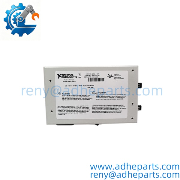
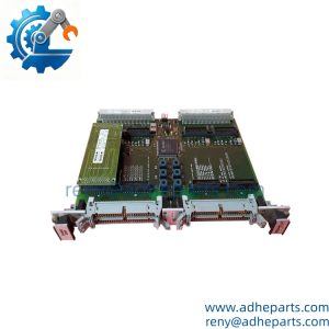
GPIB-140A
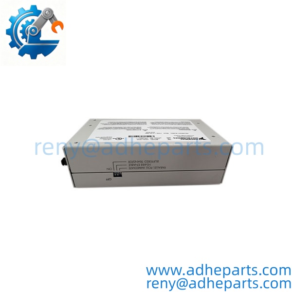
GPIB-140A
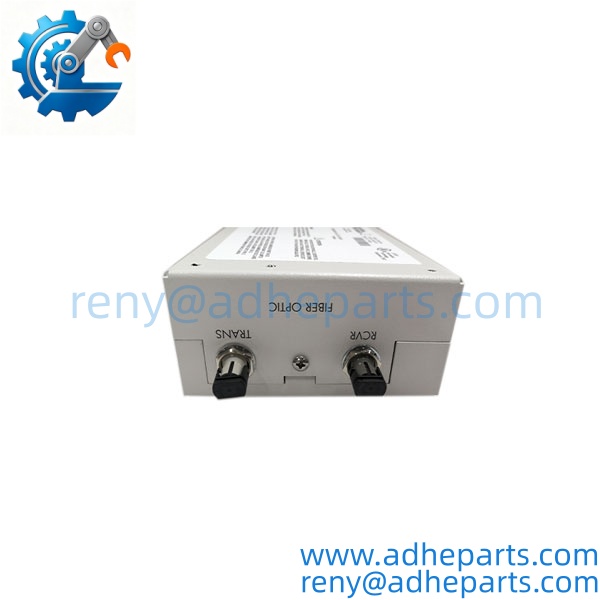
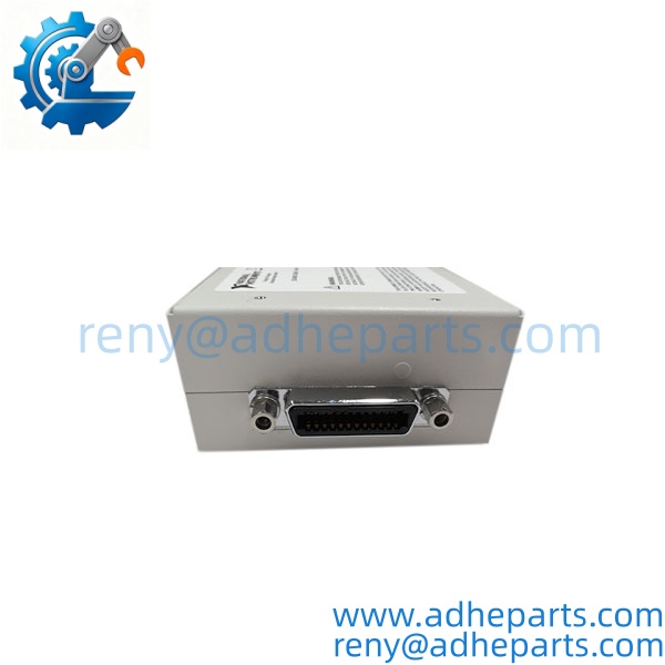
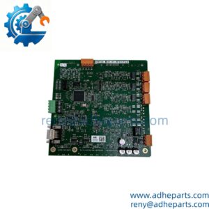
GPIB-140A
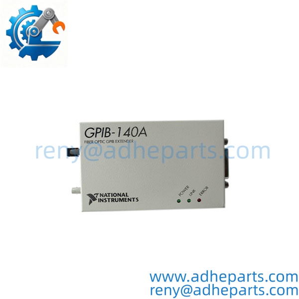
GPIB-140A
5. Application Scenarios & Field Experience
Part 1 – Narrative Paragraph
The failure that stops a test system is not always a dead instrument — it is a GPIB link that drops under electrical noise. I have seen a test cell where the GPIB bus worked fine until a nearby welder cycled, then the controller lost communication with the instruments and the test aborted. The root cause was a copper GPIB extension running parallel to power wiring. The GPIB-140A solves that by moving the link to fiber, which is immune to the interference and breaks the ground loop. The instruments and the controller stay on their own grounds, and the data path is clean.
Part 2 – Numbered List (Application Scenarios)
- Automotive Test Cells – Controller to Dynamometer Instruments – The controller sits in a control room, and the instruments are on the test floor. The extends the bus over fiber and isolates the two ground systems, preventing noise from the dynamometer drives from corrupting GPIB data.
- Aerospace – Environmental Chamber Instrumentation – Instruments inside a chamber are separated from the controller by distance and a grounded chamber wall. The fiber link passes through a bulkhead and provides the isolation required to keep the measurement clean.
- Semiconductor – Fab Floor to Equipment Rack – GPIB instruments on the fab floor connect to a controller in a remote rack. The fiber extension avoids the ground loops and EMI that plague copper runs in a fab environment.
- Power Generation – Turbine Test Stand – The controller is in a control room, and the sensors and instruments are on the test stand. The links them over fiber, and the isolation protects the instruments from the high common-mode voltages present during generator testing.
Part 3 – Short Field Story
A gas turbine test facility had a GPIB-based data acquisition system that would lose communication with the instruments every time the ignition system fired. The crew had replaced the GPIB cable and the controller card, and the dropouts continued. We recommended a pair. The fiber link replaced the long copper run and provided isolation between the test stand and the control room. The dropouts stopped. The ignition noise had been coupling into the copper GPIB cable — the fiber link was immune.
6. Standard Operating Procedure (SOP) for Quality Control
- Visual & Origin Inspection – We verify the National Instruments marking, the model string, and the date code. We inspect the GPIB connectors for bent pins and the fiber connectors for damage or contamination. A unit with a damaged connector or a cracked housing is rejected.
- Pair Matching Documentation – We verify that the local and remote units are a matched pair and record the firmware revision of each. That record ships with the set so you can compare it against the units you are replacing.
- Power-Up Self-Test – Each unit is powered on a bench fixture. We verify the power LED illuminates and the unit initializes without a fault.
- Fiber Link Test – We connect the local and remote units with a test fiber cable and verify the link establishes. We measure the link status and confirm the units communicate.
- GPIB Communication Test – We connect a GPIB controller to one unit and a GPIB instrument to the other. We run a continuous data transfer loop and log any errors. Zero errors over the test period is the pass criterion.
- Isolation Test – We apply the rated isolation voltage between the local and remote GPIB grounds. Leakage current must stay below the datasheet limit.
- Fiber Connector Inspection – We inspect and clean the fiber connectors per the OEM procedure to ensure low insertion loss.
- ESD-Safe Packaging – Each unit is wrapped in anti-static film, seated in a foam insert with the connectors protected, and packed in a double-wall carton with static warning labels.
7. Frequently Asked Questions (FAQ)
Q1: Can I use just one unit, or do I need a pair?
A: The is designed to work as a pair — a local unit and a remote unit connected by fiber. You cannot use a single unit to extend the bus. If you are replacing a failed unit, you must match it to the existing partner unit in terms of revision and fiber type. We can supply a matched pair if you need both.
Q2: What fiber cable does the require?
A: The units are built for multimode fiber with a specific connector type. I cannot confirm the exact fiber type and connector from the model number alone. Check the connector on your existing units and the fiber cable you have installed. If you send us a photo of the fiber connector, we can confirm the match before you order.
Q3: What is the maximum distance the can extend?
A: The is specified for up to 2 km over multimode fiber, but the actual limit depends on the fiber type and the link budget. Verify the maximum distance against the OEM datasheet for your specific fiber. In practice, most industrial installations use a few hundred meters.
Q4: What is the warranty on this unit?
A: We offer a 12-month warranty from the ship date. It covers power supply failure, GPIB transceiver failure, and fiber link failure under normal operating conditions. It does not cover damage from incorrect fiber connection, contaminated fiber connectors, or physical damage to the GPIB connector. We test each unit in a pair before it ships.
Q5: Any installation pitfalls I should watch for?
A: Four. First, verify the fiber type and connector match the units — a mismatched fiber will not establish a link. Second, clean the fiber connectors before mating; contamination is the most common cause of a weak link. Third, verify the GPIB device count and cable length on each side does not exceed the IEEE-488 limits. Fourth, after installation, run a full data transfer test before returning the system to service. A link that powers up is not necessarily passing data without errors.