Description
Note: Many products are not yet listed. Please contact us for more product information. Our supply channels are constantly expanding, and we currently have 20 stable shared supply channels. Please confirm the model, product, price, and all other necessary information with customer service before placing an order. We offer new, refurbished, and used products, and prices are adjusted according to the year of the item you require.
3. Key Technical Specifications
| Parameter | Value |
|---|---|
| Model | IS215ACLEH1B |
| Brand | GE (General Electric / GE Vernova) |
| Product Family | Speedtronic Mark VI / Mark VIe / EX2100e |
| Board Type | Application Control Layer (ACL) Module |
| Processor | Intel 486 DX4, 100 MHz (fourth-generation) |
| L1 Cache | 16 KB (internal, running at 100 MHz core speed) |
| L2 Cache | 128 KB (external, controlled by the PCI controller, 152 NC cache line) |
| DRAM | 8 MB (verify on your board label) |
| BIOS Flash | 4 MB |
| Ethernet Ports | 1 x 10BaseT (RJ45, IRQ 5 initialized) |
| Serial Ports | 2 x COM ports (COM1, COM2) |
| Backplane Interface | P1, 4-row 128-pin connector — VME-style |
| Rack Position | Occupies two half-slots |
| ISBus Connectors | Two ISBus connectors on front faceplate |
| Front Panel Indicators | 4 function LEDs, 8 status LEDs, 4 ISBus LEDs |
| Front Panel Controls | 1 x reset switch |
| Power Consumption | 5 W typical |
| Input Voltage | 125V DC (verify on unit label) |
| Operating System | QNX4 real-time operating system (RTOS) for deterministic logic execution |
| Redundancy Support | Simplex, Duplex (dual-module hot backup, fault switching time <50ms), and Triple Modular Redundant (TMR) |
| MTBF | 414,248 hours |
| Operating Temperature | –30 °C to +65 °C (–22 °F to +149 °F) |
| Storage Temperature | –40 °C to +85 °C (typical) |
| Humidity | 5% – 95% RH, non-condensing |
| Weight | Approx. 0.45 kg (1 lb) |
| Dimensions | Approx. 23.5 cm H x 10.8 cm W (board size) |
| Country of Origin | USA |
| Certifications | CE, UL, CSA — verify on the specific unit’s label |
4. Product Introduction
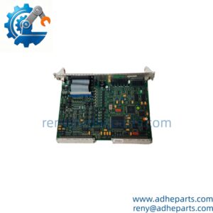
The GE IS215ACLEH1B is an Application Control Layer (ACL) module for the Speedtronic Mark VI and EX2100e turbine control systems. It serves as the system’s central computational engine, executing real-time control algorithms and managing high-level logic for turbine operation. The “ACLE” designation indicates it is an “Enhanced” version, featuring a faster 486 DX4 processor at 100 MHz and expanded memory capacity compared to standard ACL boards.
The engineering value is the combination of the QNX4 real-time operating system, the dual-redundant power architecture, and the comprehensive signal processing capability. The board receives analog signals (temperature, pressure, flow) and digital signals (device status, alarm contacts) from field sensors via the P1 backplane connector, converts them using internal ADC/DAC circuits, and executes closed-loop control of turbine parameters including valve positioning and speed feedback. The dual-redundant 24V DC power supply prevents downtime during power fluctuations, and the integrated turbine protection features provide real-time monitoring of overspeed, overtemperature, overpressure, excessive vibration, and low oil pressure.
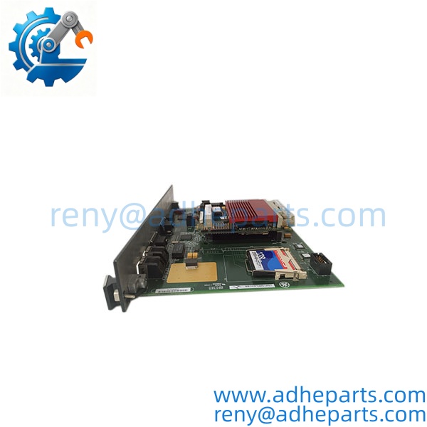
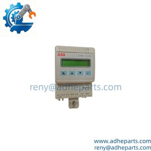
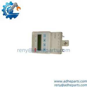
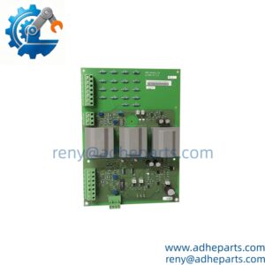
IS215ACLEH1B
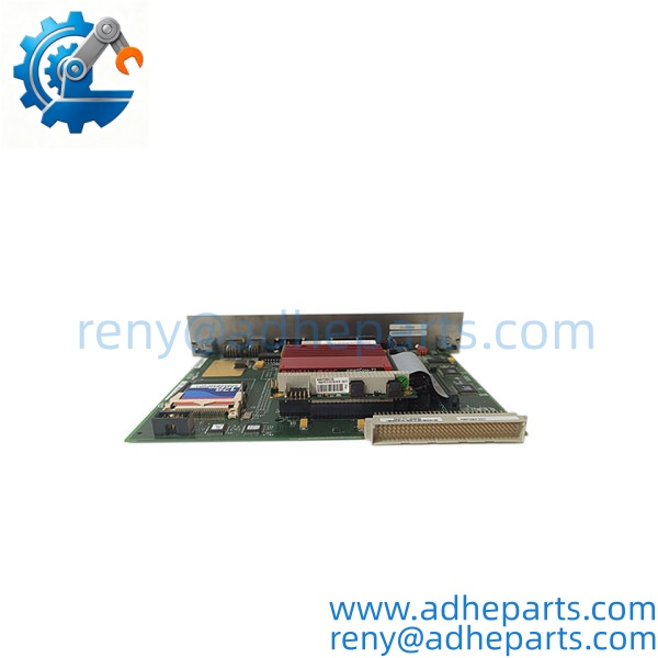
IS215ACLEH1B
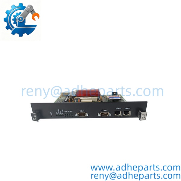
IS215ACLEH1B
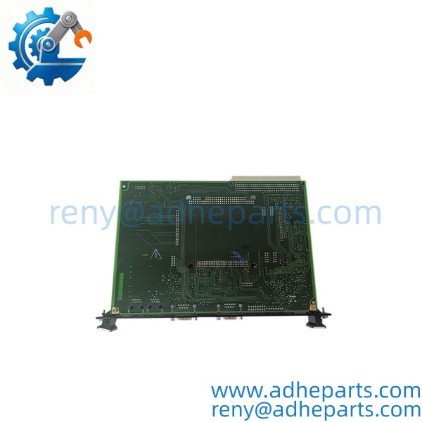
IS215ACLEH1B
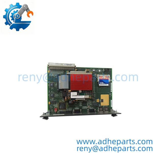
IS215ACLEH1B
5. Application Scenarios & Field Experience
Part 1 – Narrative Paragraph
The failure that hurts most on a turbine control system is not a dead processor—it is a processor that runs but produces corrupted data. The unit stays online, the operator sees readings on the HMI, and the turbine is running under control. What nobody knows is that the control layer has been quietly passing inaccurate values to the main processor. I have seen that scenario on a combined cycle plant where the ACL module had a degraded memory circuit and the fuel control valve was receiving a slightly offset position command. The unit ran for two weeks with heat rate degradation that nobody could explain. When you replace an ACL module, verify the control output against a calibrated reference before you return the turbine to service.
Part 2 – Numbered List (Application Scenarios)
- Heavy-Duty Gas Turbines – Start-Up Sequencing and Fuel Control – The ACL module manages the start-up sequence, combustion monitoring, and fuel control algorithms. It regulates turbine speed, load, pressure, and temperature in real time based on grid demand.
- Steam Turbine Control – Valve Position and Speed Governing – Used to regulate valve positions and govern turbine speed. The module adjusts steam flow and inlet valve opening in real time, maintaining a dynamic balance between output power and system requirements.
- Combined Cycle Plants – Turbine-to-DCS Bridge – Acts as a bridge between the turbine controllers and the plant-wide DCS, facilitating communication between the control layer and the operator HMI.
- Generator Excitation Control – EX2100e Series – Used in the EX2100e excitation control system to supervise excitation parameters and synchronization logic, ensuring efficient and stable generator operation.
Part 3 – Short Field Story
A 400 MW coal-fired power plant in Pennsylvania had a Mark V turbine control system that was causing two to three unplanned shutdowns monthly due to signal latency between the turbine controllers and third-party sensors. After deploying the IS215ACLEH1B, the plant eliminated 90% of these false shutdowns. The module’s ability to process vibration, oil pressure, and temperature signals in real time—while translating data between incompatible protocols—solved the core pain point of communication bottlenecks. Plant managers reported a 15% reduction in maintenance labor costs and a 2% increase in energy generation efficiency.
6. Standard Operating Procedure (SOP) for Quality Control
Every IS215ACLEH1B module passes this QC sequence:
- Visual & Origin Inspection – We verify the GE marking, the IS215ACLEH1B model string, and the date code. We inspect the P1 backplane connector for bent pins and the front-panel ISBus connectors for damage. A board with a cracked connector shroud or evidence of moisture ingress is rejected.
- Revision and Firmware Documentation – We read and photograph the full model string, the firmware revision, and the board ID number printed on the faceplate. That record ships with the module so you can compare it against the unit you are replacing.
- Backplane Fit Verification – Each module is seated in a Mark VI test rack to confirm the P1 128-pin connector engages fully and the front-panel captive screws secure the board for proper grounding.
- Power-Up Self-Test – The module is powered in a live rack and we verify it completes its boot sequence, the Run LED indicates normal operation, and the board initializes without a fault.
- Communication Port Test – We verify the 10BaseT Ethernet port with a loopback and confirm link and throughput. We verify both COM ports with a test partner.
- ISBus Communication Test – The module is connected to a Mark VI test network and we verify it communicates across the ISBus connectors at the specified data rate. We run a continuous exchange loop and log any dropped frames.
- Signal Path Verification – We verify the module’s analog and digital signal path against a calibrated test fixture and confirm the control outputs match the commanded values.
- Diagnostic Function Test – We verify the module reports a fault to the controller when a simulated error condition is present. A module that controls correctly but does not report faults is not acceptable for turbine protection.
- ESD-Safe Packaging – The board is wrapped in anti-static film, seated in a conductive foam insert with the connectors protected by rigid shrouds, and packed in a double-wall carton with static warning labels.
7. Frequently Asked Questions (FAQ)
Q1: What is the difference between the IS215ACLEH1B and the IS215ACLEH1A?
A: The “B” revision typically includes hardware optimizations or updated electronic components compared to the “A” version. The IS215ACLEH1A runs a 266 MHz CPU, while the runs a 400 MHz CPU. While usually backward compatible, always check the release notes in the GE ToolboxST software for specific firmware dependencies before substituting one for the other.
Q2: Will this board work in my Mark VI rack without a firmware change?
A: Only if the firmware revision matches or is compatible with the system project database in GE ToolboxST. The firmware revision governs the board’s communication behavior and its compatibility with the main processor. A mismatched revision can initialize and still produce control errors under load. Read the firmware revision off your existing board and compare it to the replacement before you order.
Q3: What is the warranty on this board?
A: We offer a 12-month warranty from the ship date. It covers component failure, backplane connector failure, Ethernet port failure, and ISBus communication failure under normal operating conditions. It does not cover damage from hot-swapping the board with the rack energized, bent pins from forced insertion, or ESD damage from handling without a wrist strap. The board is a surface-mount electronic assembly—repairs should only be performed by certified service centers.
Q4: Do you have this exact board in stock?
A: Mark VI and EX2100e inventory moves quickly, and stock varies by revision. Confirm availability before you plan an outage. If we are out of the revision you need, we will tell you what we actually have rather than quote a date we cannot hold.
Q5: Any installation pitfalls I should watch for?
A: Four. First, power down the VME chassis before inserting or removing the board—these boards are not hot-swap capable in an un-redundant rack. Second, record the firmware revision and board ID from the old module before you remove it. Third, verify the firmware version on the board matches the project requirements in ToolboxST before you power up. Fourth, after the swap, monitor the Run LED and verify the control output against a calibrated reference before you return the turbine to service. A board that powers up is not necessarily executing control correctly.