Description
Note: Many products are not yet listed. Please contact us for more product information. Our supply channels are constantly expanding, and we currently have 20 stable shared supply channels. Please confirm the model, product, price, and all other necessary information with customer service before placing an order. We offer new, refurbished, and used products, and prices are adjusted according to the year of the item you require.
3) Key Technical Specifications
| Specification | Details |
|---|---|
| Manufacturer | General Electric |
| Model | IS200VCRCH1B |
| Functional Designation | VCRC |
| Control Platform | Mark VI Speedtronic |
| Board Type | VME discrete I/O processor board |
| Contact Input Capacity | 48 grouped contact inputs |
| Relay Output Capacity | 24 relay outputs through two compatible TRLY boards |
| Rack Interface | VME backplane |
| Board Occupancy | One VME slot |
| I/O Processing | Onboard processor; identified as TMS320C32 in technical reseller documentation |
| Event Recording | Contact transitions timestamped to 1 ms, as documented by technical reseller sources |
| Input-Side Hardware | Compatible TBCI boards; simplex arrangements may use DTCI |
| Output-Side Hardware | Compatible TRLY boards; simplex arrangements may use DRLY |
| System Configuration | Mark VI hardware and I/O configuration dependent |
The channel counts describe the documented system interface and should not be interpreted as 48 inputs and 24 relay contacts physically located on the VCRC board itself. Field connections and relay switching depend on the associated terminal and relay boards.
4) Product Introduction — Anti-Template
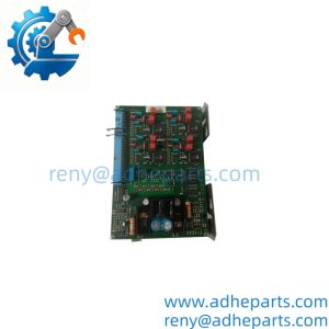
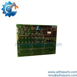
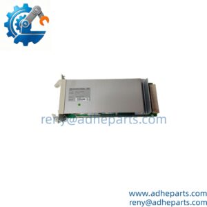
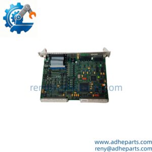
The GE IS200VCRCH1B VCRC board is part of the Mark VI Speedtronic turbine control system. It provides the processing and interface path for grouped contact inputs and relay-output commands used in turbine sequencing, equipment status monitoring, permissive logic, and related control functions.
For a maintenance replacement, check the entire I/O path rather than the board alone. The connected terminal-board type, relay-board arrangement, VME slot, and downloaded configuration all matter. This is legacy turbine-control hardware, so a matching catalog number is the starting point—not the end of compatibility verification.
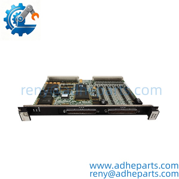
IS200VCRCH1B
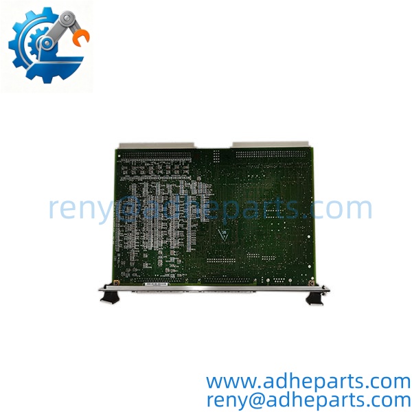
IS200VCRCH1B
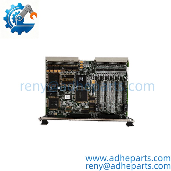
IS200VCRCH1B
5) QC, Procurement & Logistics SOP
1) Incoming Identification
Before shipment, inspect and record:
- Full part number: IS200VCRCH1B
- Board designation and hardware revision
- Serial number and identification labels
- PCB condition, connectors, and component surfaces
- Evidence of corrosion, overheating, or previous repair
- Connector alignment and any damaged pins
- Packaging and ESD protection status
Photograph the complete board and its labels so the buyer can confirm the part number before dispatch.
2) Functional Verification
Testing should use an appropriate Mark VI test setup or compatible system configuration. Where available, verification should include:
- Board recognition in the intended VME rack
- Startup and diagnostic status
- Communication with the control system
- Correct recognition of connected terminal-board types
- Contact-input status acquisition
- Relay-output command path using compatible relay hardware
- Diagnostic and configuration checks
A visual inspection alone cannot establish full operational condition. If testing is performed without the customer’s complete system, clearly distinguish bench inspection from system-level functional testing.
3) Terminal Board and Relay Hardware Verification
The VCRC board’s field interface depends on the connected hardware. Confirm whether the installation uses TBCI and TRLY boards or the intended simplex DTCI/DRLY arrangement. Check the board identification and connector assignments against the system configuration before installation.
4) Configuration and Replacement Procedure
Before removing the original board, document its rack position, connected cables, terminal-board types, and relevant Mark VI configuration. Follow the approved turbine-control maintenance procedure, including required isolation and shutdown controls.
After installation, verify hardware recognition and I/O diagnostics before returning the equipment to service. Do not assume that a replacement automatically inherits the existing configuration.
5) ESD Packaging and Global Logistics
Use ESD-safe packaging for the board, protect connectors against impact, and place the unit in a rigid outer carton with adequate cushioning. For export shipments, confirm the commercial description, customs classification, country-of-origin documentation, applicable export requirements, Incoterms, insurance, and lead time.
Suggested commercial description:
GE Mark VI VCRC VME Discrete Input/Output Control Board, Model IS200VCRCH1B
6) Technical Pitfalls & Integration Warnings
1) Do Not Confuse VCRC with VCCC
The VCRC provides a single-slot arrangement without the VCCC-style daughterboard. The board and its cable arrangement differ, so do not assume a VCCC assembly can replace a VCRC board directly.
2) Verify the Connected I/O Hardware
The documented arrangement uses TBCI terminal boards for grouped contact inputs and TRLY relay boards for outputs. Simplex configurations may use DTCI and DRLY. Verify the actual installed configuration before selecting a replacement.
3) Confirm Relay Outputs Are Provided Through Compatible Relay Boards
Do not interpret the stated 24 relay-output capacity as proof that the VCRC itself contains 24 onboard relay contacts. The output path depends on compatible relay hardware and the system’s wiring arrangement.
4) Check Hardware Revision and Downloaded Configuration
The Mark VI configuration must match the board type, terminal-board arrangement, and connector assignments. A board that physically fits the rack may still report configuration or identification faults if the connected hardware does not match the expected setup.
5) Preserve Turbine Protection and Interlock Integrity
Contact inputs and relay outputs may participate in permissive, alarm, shutdown, or auxiliary-control sequences. Verify signal states and the intended output path under an approved maintenance procedure before restoring normal operation. Never bypass turbine safety logic simply to clear a board fault.
6) Firmware and Configuration Must Be Considered Together
This is not a generic PLC I/O card. Confirm compatibility with the installed Mark VI hardware and configuration tools, and review relevant diagnostics before changing firmware or application settings. The exact firmware requirements should be established from the applicable system documentation.
7) Frequently Asked Questions
Q1: What is the GE IS200VCRCH1B?
It is a VCRC VME discrete I/O board used in GE Mark VI Speedtronic turbine control systems.
Q2: How many inputs and outputs does it support?
Technical documentation from specialist suppliers describes 48 grouped contact inputs and up to 24 relay outputs through two compatible TRLY boards. The physical field interfaces depend on the associated terminal and relay hardware.
Q3: Is the IS200VCRCH1B a standalone relay output module?
No. It is a VME control/I/O board. Relay switching is provided through compatible relay hardware in the configured system.
Q4: Which terminal boards should I check before ordering?
Check the installed TBCI and TRLY boards. If the system uses a simplex arrangement, verify whether DTCI and DRLY interfaces are specified for that configuration.
Q5: Can I replace a VCCC board with an ?
Do not assume direct interchangeability. The VCRC and VCCC differ in their board arrangement and cable interfaces. Confirm the system design and required relay-output connections before substitution.
Q6: What information should I provide for a replacement quotation?
Provide the complete part number, hardware revision, nameplate or PCB photos, Mark VI rack information, connected terminal-board and relay-board models, and any diagnostic fault messages.
Q7: What should be checked after installation?
Verify board recognition, diagnostic status, terminal-board identification, contact-input states, relay-output paths, and the downloaded configuration. Perform the checks under the approved turbine-control maintenance procedure before returning the system to service.