Description
Note: Many products are not yet listed. Please contact us for more product information. Our supply channels are constantly expanding, and we currently have 20 stable shared supply channels. Please confirm the model, product, price, and all other necessary information with customer service before placing an order. We offer new, refurbished, and used products, and prices are adjusted according to the year of the item you require.
Product Introduction
Loss of scaled generator‑protection signals can trigger false trips on combined‑cycle units during normal grid‑load swings.
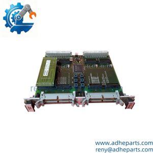
This TCEB board sits between field‑connected PTBA hardware and the Mark V protective core. It steps down high‑magnitude CT‑PT secondary currents and voltages before delivery to processing cards, while carrying critical overspeed‑trip and flame‑detect signal pathways. Board‑mounted transformers set fixed scaling ratios —though your mileage may vary depending on site‑specific CT‑PT ratios configured in control logic.
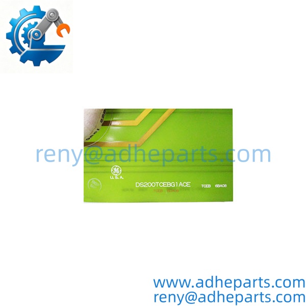
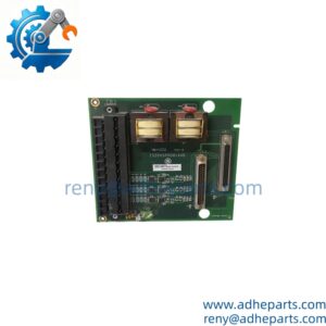
DS200TCEBG1ACE
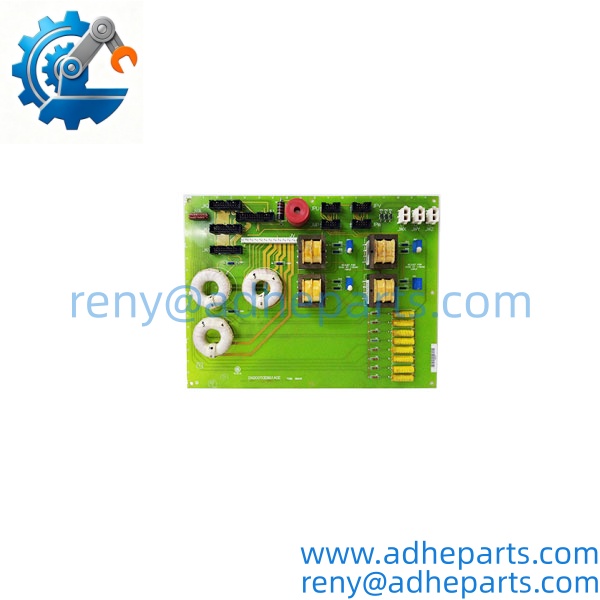
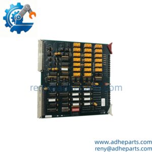
DS200TCEBG1ACE
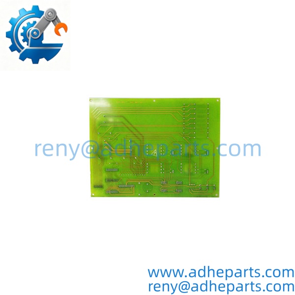
DS200TCEBG1ACE
Key Technical Specifications
| Parameter | Value |
|---|---|
| System Compatibility | GE Speedtronic Mark V Turbine Control |
| Form Factor | 6U rack‑mount PCB for Mark V core slots |
| Signal Functions | CT‑PT signal scaling, overspeed / flame‑detection signal routing |
| On‑Board Components | 4 integrated current‑sense transformers, fuse bank, filter resistors |
| Interboard Connectors | 3 bayonet‑lock connectors (JWX, JWY, JWZ), multi‑pin header banks |
| Conformal Coating | Factory‑applied protective conformal coating |
| Operating Ambient | 0 °C to +60 °C cabinet temperature, non‑condensing humidity |
| Status Feedback | No dedicated on‑board LEDs; health inferred via upstream system alarms |
| Mounting | Standard Mark V card‑cage with ejector latches |
| Power Source | Backplane‑supplied logic and auxiliary power |
Field Application & Technical Pitfalls (The Engineer’s Guide)
This termination expander supports three high‑risk plant scenarios. Combined‑cycle generator‑protection racks use it for bus‑voltage and line‑current signal conditioning. Simple‑cycle peaker‑plant cabinets route hard‑wired overspeed‑trip paths through its trace layers. Cogeneration turbine packages rely on its UV‑flame‑detect power routing for continuous‑burner supervision.
Critical technical pitfalls during replacement:
- Bayonet connector mis‑seating: The three bayonet lock connectors sit along the right‑side board edge. Partial engagement creates high‑impedance signal paths that only show up under high‑generator‑load conditions. Twist each bayonet until you feel a positive click.
- CT‑PT scaling ratio mismatch: Different TCEB suffix variants carry different internal transformer turns ratios. DS200TCEBG1ACE is not drop‑in‑compatible with all TCEB part suffixes; mismatched ratios produce distorted current‑voltage readings.
- ESD damage to low‑level transformer windings: Even with rack power removed, static discharge can degrade fine‑gauge transformer windings. Conformal coating offers minimal shielding against static events.
A site maintenance crew swapped a suspected faulty TCEB during a short planned outage. They mated the three bayonet connectors by hand without applying full locking twist and installed a board with a mismatched transformer suffix. After turbine synchronization, generator‑protection alarms appeared only above 70 % electrical load. Technicians spent multiple shifts chasing logic‑configuration errors before discovering incomplete bayonet locking and wrong‑variant hardware. Always cross‑verify the full part‑number suffix and confirm each bayonet connector locks fully before closing cabinet doors.
Quality Control (QC) SOP & Transparency
- Inbound Verification: Match full part‑number suffix DS200TCEBG1ACE, silkscreen marking, and serial number to OEM packing documentation. Inspect conformal coating for chipping, burn marks, or repair‑solder residues. Check bayonet connector shells for bending or cracked plastic housings. Inspect transformer windings for visual damage.
- Live Rig Testing: Seat board inside Mark V test cage, energize rack backplane supplies. Inject simulated CT‑PT secondary signals; validate scaled output levels against OEM reference values. Cycle each bayonet connector multiple times to verify stable signal transfer. Confirm no intermittent opens across signal traces.
- Parameter Testing: Run continuity checks across every bayonet‑connector pin and header contact. Measure winding resistance for each on‑board current transformer and compare against published reference ranges. Perform insulation‑resistance testing between signal paths and chassis ground.
- Final QA & Packaging: Apply protective caps to bayonet‑connector interfaces. Seal board inside static‑shield anti‑static bag. Affix QC‑passed label including test‑timestamp and verified full part suffix. Pack with rigid foam padding to prevent transformer‑winding mechanical shock in transit.
Frequently Asked Questions (FAQ)
Can I hot‑swap DS200TCEBG1ACE while the Mark V rack stays powered?No. This legacy Mark V hardware provides zero hot‑swap capability. Full rack‑control‑power shutdown is mandatory before removal or insertion. Live‑power card handling risks backplane trace burnout and transformer‑winding damage.
What Mark V core slots accept DS200TCEBG1ACE?Designed for the P1 protective core slot within Mark V racks. It will not operate in Mark VI or Mark VIe hardware platforms. Verify exact load capacity with the OEM datasheet before integration.
What warranty coverage applies for new‑surplus DS200TCEBG1ACE boards?Twelve‑month functional warranty is provided. Warranty excludes damage from improper bayonet‑connector seating, ESD events, cabinet over‑temperature, or installation of wrong‑suffix hardware variants. Intact factory conformal‑coating shelf scuffs do not void coverage.
How do I tell genuine OEM surplus hardware from rebuilt aftermarket copies?Genuine OEM boards have uniform factory conformal‑coating coverage, consistent transformer‑component placement, and crisp silkscreen part‑number marking. Rebuilt units often show hand‑touched solder joints, patch‑repaired traces, or non‑original replacement transformers. Well, technically some OEM‑refurbished units exist, so bench signal‑ratio testing serves as final validation.
Will I need to adjust generator‑protection setpoints after board replacement?If you install the exact same suffix variant, existing protection‑logic settings normally stay valid. Mismatched suffix hardware forces re‑tuning of CT‑PT scaling parameters inside the turbine‑control database.
What field symptoms point to a failing TCEB board?Intermittent generator‑protection alarms, wandering line‑current or bus‑voltage measurements, sporadic flame‑detect drop‑outs, and trips that activate only under high electrical load. Many of these symptoms also point to PTBA‑board or wiring faults, so bench testing is required for confirmation.
What happens once DS200TCEBG1ACE surplus stock is exhausted?This is a discontinued legacy Mark V component. Once existing surplus inventory depletes, sourcing lead‑times expand sharply. Confirm stock availability well ahead of scheduled generator‑turbine outages.