Description
Note: Many products are not yet listed. Please contact us for more product information. Our supply channels are constantly expanding, and we currently have 20 stable shared supply channels. Please confirm the model, product, price, and all other necessary information with customer service before placing an order. We offer new, refurbished, and used products, and prices are adjusted according to the year of the item you require.
Product Introduction (Anti-Template)
The GE 531X305NTBANG1 is an NTB/3TB Drive Terminal Board designed to provide the physical interface between a GE drive or exciter control system and external signal-level wiring. Rather than acting as the main processor, the board handles customer connection terminals and associated interface circuitry, while also carrying configurable jumpers, potentiometers, relay interfaces, encoder connections, and auxiliary power outputs. GE documentation describes the 531X305NTB as the terminal board containing customer connection terminals for most signal-level I/O.
The board can be encountered in legacy GE drive and excitation equipment, including DC2000/ACDC2000-related architectures and GE exciter applications. Its exact wiring depends on the equipment configuration, so 531X305NTBANG1 should be treated as a system-specific terminal/interface board rather than a generic I/O card. The complete board number and existing jumper/potentiometer configuration should be checked before replacement.
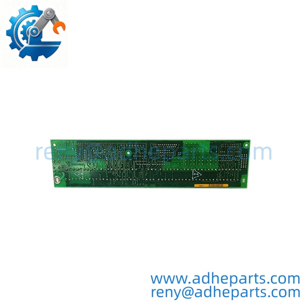
531X305NTBANG1
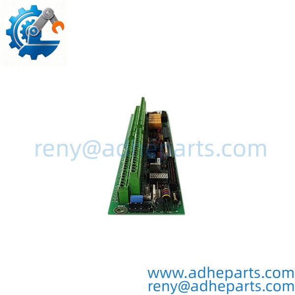
531X305NTBANG1
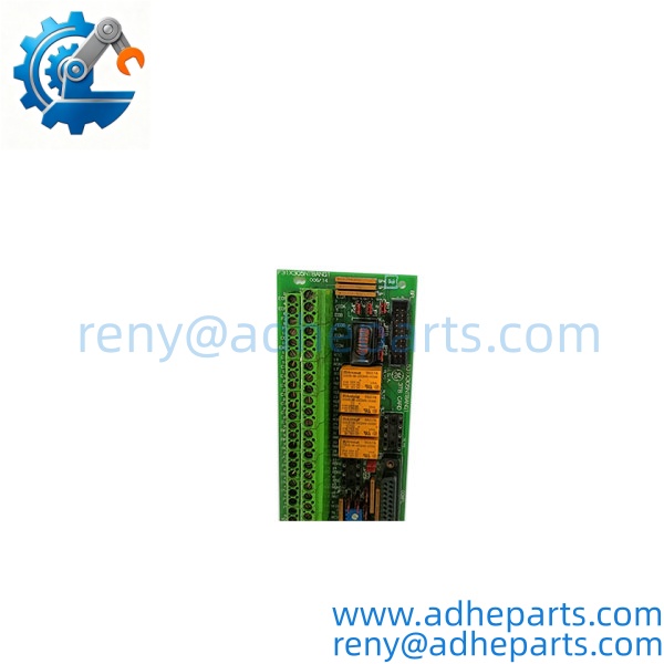
531X305NTBANG1
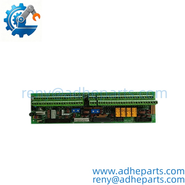
531X305NTBANG1
Key Technical Specifications
| Parameter | Specification |
|---|---|
| Manufacturer | GE General Electric |
| Series | 531X |
| Model | 531X305NTBANG1 |
| Board Type | NTB/3TB Drive Terminal Board |
| Primary Function | Signal-level I/O and customer interface |
| Regulated Power Outputs | 5 VDC, 15 VDC |
| Unregulated Power Outputs | 24 VDC, 125 VAC |
| Encoder Support | 5 V / 15 V configurable |
| Relay Outputs | 7 relays |
| Relay Contact Rating | Up to 120 VAC, application-dependent |
| Analog Interface | Low-level analog I/O |
| Configuration Hardware | Onboard jumpers and potentiometers |
| Typical Equipment | GE drive and exciter systems |
| Related Board | F31X305NTBANG1 |
| Condition | New Surplus / Refurbished |
The documented NTB/3TB architecture includes customer signal terminals, passive interface circuitry, hardware-customizing jumpers and potentiometers, and connections to other drive control boards. The GE DC2000 documentation specifically describes connections between the NTB/3TB and the SDCC and DCFB/DCFB-related circuitry.
Field Application & Technical Pitfalls (The Engineer’s Guide)
Application 1 — GE Drive Control Cabinets
The 531X305NTBANG1 provides the external terminal interface for signal-level control and feedback circuits within compatible GE drive systems. It is positioned between the controller electronics and field/customer wiring, making its terminal assignments important during maintenance.
Application 2 — Excitation Systems
The NTB/3TB board is also associated with GE exciter architectures. In these systems, the board can handle signal connections, relay interfaces, encoder-related circuitry, and auxiliary power distribution. Some supply references specifically identify the 531X305NTBANG1 with GE EX2000 excitation applications.
Application 3 — Encoder and Analog Feedback
The board provides configurable interfaces for encoder signals and low-level analog circuits. Onboard jumpers and potentiometers are therefore not merely spare configuration points—they can directly affect how feedback and control signals are interpreted by the drive system.
Pitfall 1 — Do not treat it as a standalone PLC I/O module.
The 531X305NTBANG1 is primarily a terminal/interface board. Its circuits and terminal assignments depend on the surrounding GE drive or exciter architecture.
Pitfall 2 — Record jumper and potentiometer settings before replacement.
The board contains hardware-customizing jumpers and pots. Copying the configuration from a visually similar board without checking the equipment manual can produce incorrect signal scaling or encoder configuration.
Pitfall 3 — Verify the exact terminal wiring.
The 3TB connector contains numerous customer/system connection points. GE documentation describes connections between the NTB/3TB, SDCC, DCFB/DCI-related circuitry, and customer terminals. A wiring mistake can therefore affect multiple control functions simultaneously.
Pitfall 4 — Do not assume every 531X305NTB has identical configuration.
The same basic NTB/3TB board architecture can appear across different GE drive and exciter applications. The installed equipment model and board suffix should be checked before approving a substitute.
Field lesson: A terminal board can look like one of the simplest cards in an old drive cabinet, but it often contains the configuration details that make the rest of the system work correctly. When replacing a 531X305NTBANG1, photographing the jumper positions, potentiometer settings, terminal wiring, and board markings before removal can save considerably more time than troubleshooting a misconfigured replacement later.
Quality Control (QC) SOP & Transparency
- Full Part-Number Verification — Confirm the complete identification as 531X305NTBANG1 and compare the board marking with the customer’s existing unit.
- Application Verification — Confirm the installed equipment, such as the relevant GE drive or exciter cabinet, before approving the replacement.
- Physical Inspection — Check terminal blocks, PCB traces, relays, potentiometers, jumpers, connectors, and mounting points.
- Relay Inspection — Examine all seven relay positions for overheating, cracked housings, damaged terminals, or signs of previous repair.
- Power-Circuit Inspection — Check the areas associated with the 5 VDC, 15 VDC, 24 VDC, and 125 VAC interfaces.
- Jumper Documentation — Photograph and record the original jumper configuration before dispatch whenever the customer’s original board is available.
- Potentiometer Documentation — Record the approximate original settings where these adjustments form part of the application configuration.
- Functional Testing — Where suitable test equipment is available, verify representative relay, power-output, analog-interface, and encoder-related functions.
- Final QA Record — Record part number, revision markings, physical condition, inspection results, and photographs.
- ESD-Safe Packaging — Protect the board in anti-static packaging with adequate mechanical cushioning.
FAQ
Q1: What is GE 531X305NTBANG1?
It is a 531X-series NTB/3TB Drive Terminal Board used for customer and system signal interfacing in compatible GE drive and exciter systems.
Q2: Is 531X305NTBANG1 a controller board?
No. It is primarily a terminal/interface board. The main control processor is located on other boards in the drive architecture.
Q3: What power outputs are available?
Documented specifications include regulated 5 VDC and 15 VDC outputs and unregulated 24 VDC or 125 VAC outputs.
Q4: How many relay outputs does it have?
The board has seven relay outputs. Documentation for the NTB/3TB architecture describes Form A/Form C relay arrangements, with contact ratings dependent on the specific circuit/application.
Q5: Does it support encoder signals?
Yes. The board provides configurable encoder-related circuitry, including 5 V and 15 V configurations through onboard jumpers.
Q6: Is 531X305NTBANG1 interchangeable with F31X305NTBANG1?
Some documentation identifies F31X305NTBANG1 as an alternate number for the 531X305NTBANG1. However, the complete installed-system configuration should still be checked before substitution rather than treating the two numbers as universally interchangeable.
Q7: What should I provide when requesting a replacement?
Provide the complete part number, photos of the board label and terminal strips, the GE drive/exciter model, and—ideally—photos showing the jumper and potentiometer settings. This allows the replacement to be checked against the actual installation rather than only the board family.
Q8: What condition can be supplied?
Depending on available inventory, the 531X305NTBANG1 may be sourced as new surplus or refurbished/tested stock. The quoted condition and test status should be stated clearly for each unit.