Description
Note: Many products are not yet listed. Please contact us for more product information. Our supply channels are constantly expanding, and we currently have 20 stable shared supply channels. Please confirm the model, product, price, and all other necessary information with customer service before placing an order. We offer new, refurbished, and used products, and prices are adjusted according to the year of the item you require.
3. Product Introduction
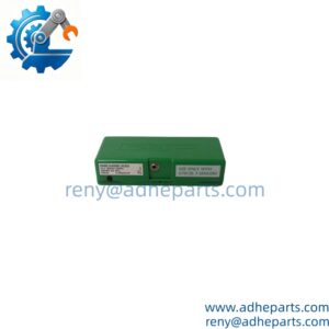
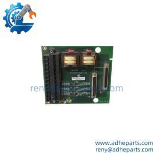
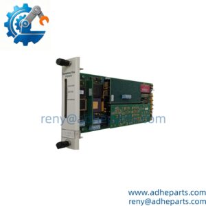
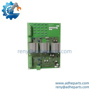
As a field termination unit in Bailey’s INFI 90 family, the 6637517A1 gives analog field wiring a clean landing point before the signal reaches the input module. It mounts near the rack, accepts current or voltage loops at screw terminals, and passes them through a cable interface to the I/O card. The practical edge is serviceability: one terminal assembly can be swapped without pulling the whole rack (—though your mileage may vary depending on the paired module and cabinet layout).
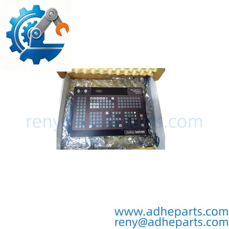
6637517A1
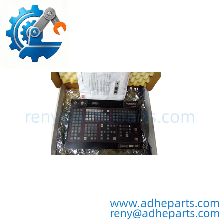
6637517A1
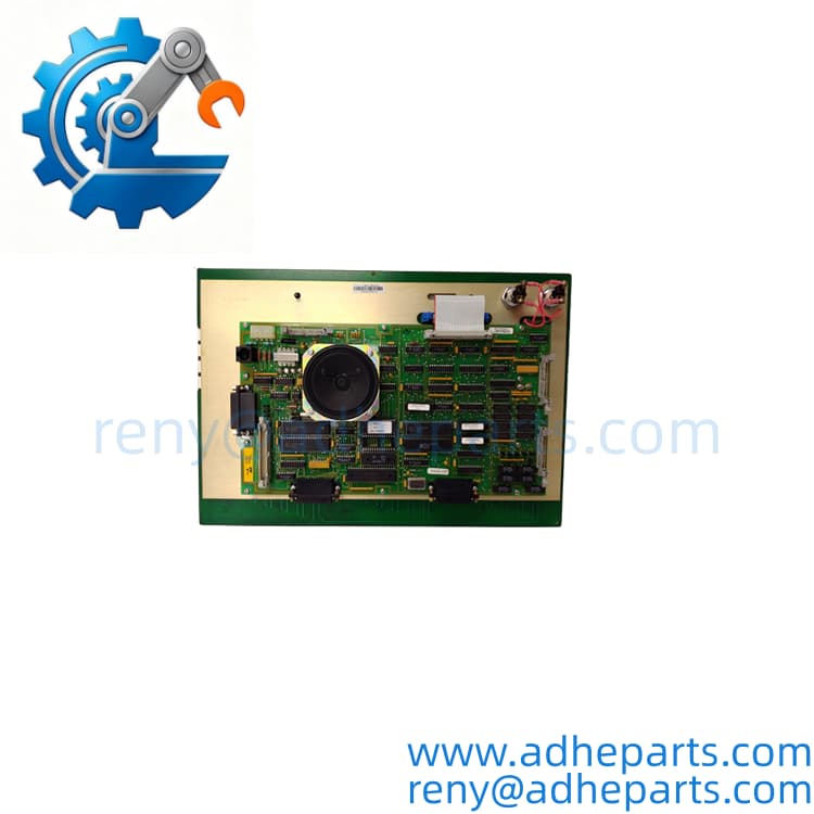
6637517A1
4. Key Technical Specifications
| Parameter | Value |
|---|---|
| Catalog Number | 6637517A1 |
| Brand | Bailey (ABB) |
| Product Type | Analog input termination unit, NTAI05-class |
| Host Platform | Bailey INFI 90 / Net 90 I/O rack — confirm paired analog input module |
| Input Channels | 16-channel class — verify exact count with OEM datasheet |
| Input Signals | 4–20 mA and 1–5 VDC class — confirm resistor and jumper configuration |
| Field Terminals | Screw terminal block — verify terminal count and wire size |
| Module Interface | Ribbon or multi-pin cable to analog input module — verify connector type and pinout |
| Mounting | DIN rail or panel mount — confirm from OEM drawing |
| Isolation | Verify field-to-logic and channel-to-channel isolation with OEM datasheet |
| Configuration | Passive termination — confirm any resistor or jumper options |
| Operating Temperature | Verify exact range with OEM datasheet |
5. Field Application & Technical Pitfalls (The Engineer’s Guide)
Where this assembly is critical:
- Legacy Bailey INFI 90 racks in power and water plants, where analog transmitters feed flow, pressure, and level loops into the control system.
- Remote analog cabinets where field wiring lands on a termination assembly before the cable run to the I/O rack.
- Process skids kept alive because the mechanical side runs fine and a controls migration is a capital project, not a maintenance order.
Three pitfalls that bite during replacement:
- Resistor and jumper configuration for current versus voltage. Warning: a termination set for 1–5 VDC will scale a 4–20 mA loop wrong, and the reading can look plausible at one point while failing at another. Confirm the resistor pack and jumper positions against the paired module and the loop drawing.
- Shield landing and loop common. Warning: grounding the shield at both ends creates a ground loop that shows up as noise on a slow trend, not as a hard fault. Land the shield per the OEM drawing, and confirm the loop common is not tied to a different reference than the I/O module expects.
- Cable pinout and module pairing. Warning: the connector may fit while the pinout maps channels differently. Photograph the third terminal block from the left before removal, and check the cable label against the paired module. Do not assume live removal is allowed — remove rack power and ground yourself before touching the connector.
Lesson learned: A technician replaced a failed termination assembly, powered up, and watched a flow loop read about 25% high. Root cause — the replacement carried a voltage-input resistor pack while the field device was a 4–20 mA transmitter. The assembly was good; the input configuration was not. One shift of troubleshooting for a five-minute label check.
6. Quality Control (QC) SOP & Transparency
- Inbound Verification. Each assembly is checked against the OEM packing list, label typography, catalog number, serial number format, and date-code range. Resistor and jumper configuration are logged before the unit enters stock.
- Live Rig Testing. The assembly is paired with a compatible Bailey analog input module in an INFI 90 test rack. A loop calibrator injects 4, 12, and 20 mA plus 1, 3, and 5 VDC, and we verify the corresponding readings at the module.
- Parameter Testing. Terminal continuity, resistor values, insulation resistance, and connector pinout are checked against the OEM datasheet where published. Undocumented values are flagged for buyer confirmation rather than guessed.
- Final QA & Packaging. The assembly ships in an anti-static bag with a QC-passed label, a test record showing the input configuration and readings we verified, and photos of the terminal layout when available.
7. Frequently Asked Questions (FAQ)
Can I hot-swap this termination assembly? No. Remove rack power and confirm the loop is isolated before replacement. Live removal can inject a false signal or damage the paired input module.
How do I confirm it matches my rack? Send the paired Bailey module part number, old label photo, loop drawing, and terminal wiring photos. We cross-check the catalog number and test record before shipping. Exact fit depends on the module pairing and input configuration, not just the termination part number.
What’s the warranty? 12 months from delivery for functional failure under normal operation. Fuses and other consumables carry a 90-day replacement guarantee.
How can I tell genuine OEM from refurbished? Genuine units carry the original Bailey label with consistent typography and a traceable serial number. Refurbished units carry our QC tag in addition to the OEM label, and we disclose condition on the quote.
Does it ship with the cable to the I/O module? No. The termination assembly ships as the unit only unless the quote says otherwise. Confirm connector type and pinout against the OEM drawing.
Does it need configuration software? No address or software setup applies to a passive termination assembly. It does have resistor or jumper options for current versus voltage input, and those must match the field device and paired module.
What do you need to quote the right replacement? Paired module part number, old label photo, loop drawing, and terminal wiring photos. That five-minute upload prevents most wrong-part returns.