Description
Note: Many products are not yet listed. Please contact us for more product information. Our supply channels are constantly expanding, and we currently have 20 stable shared supply channels. Please confirm the model, product, price, and all other necessary information with customer service before placing an order. We offer new, refurbished, and used products, and prices are adjusted according to the year of the item you require.
Key Technical Specifications
Do not order against this table alone. I cannot confirm the board type, channel count, or electrical ratings from the model number. Match every line against the OEM datasheet for your specific drive or system.
| Parameter | Value |
|---|---|
| Model | 503-26606-21 |
| Brand | Danaher Motion |
| Product Family | Verify — confirm the host drive or motion control system |
| Board Type | Verify — confirm whether this is a drive control board, interface card, or controller component |
| Compatible System | Verify — confirm the drive model, rack, or cabinet |
| Input / Output Signal Type | Verify with OEM datasheet |
| Signal Range | Verify with OEM datasheet |
| Supply Voltage | Verify — logic rail or power stage voltage |
| Current Rating | Verify with OEM datasheet |
| Isolation | Verify — field side to logic side |
| Connector Type | Verify — connector arrangement varies by build |
| Status Indicators | Verify — LED arrangement varies by revision |
| Jumper / Switch Settings | Verify — record from your existing board before ordering |
| Operating Temperature | Verify for your cabinet ambient |
| Storage Temperature | –40 °C to +85 °C (typical — verify) |
| Humidity | 5% – 95% RH, non-condensing |
| Mounting | Verify — rack, cabinet slot, or panel |
| Weight | Verify with OEM datasheet |
| Certifications | Verify on the specific unit’s label |
Product Introduction
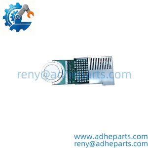
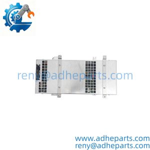
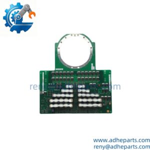
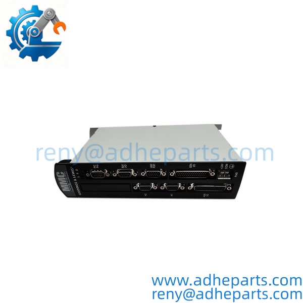
The Danaher Motion 503-26606-21 is an industrial motion control board from the Danaher Motion group. Danaher Motion built servo drives, motors, and motion controllers under the Kollmorgen and Thomson brands, and the 503- prefix appears across their drive and interface hardware. The exact function of this board depends on the drive or system it serves — I cannot tell from the model number alone whether it is a drive control board, an interface card, or a controller component.
Here is what I can tell you as a straight answer: on Danaher Motion hardware, compatibility is drive-model-specific and firmware-specific. A board that fits one drive may not initialize in another if the firmware revision is different or the backplane pinout varies. Before you order, read the label on the existing board and cross-reference it against the OEM datasheet for your drive model. If you send me a photo of the board and the drive model plate, I will confirm what you are looking at.
Application Scenarios & Field Experience
Part 1 – Narrative Paragraph
The failure that costs the most downtime on a servo drive board is a firmware mismatch that passes a bench check and still fails in the cabinet. I have seen a plant replace a drive board with a newer revision and then chase a “drive fault” for a week. The board was fine. The drive firmware expected a specific revision, and the new one would not initialize. On Danaher Motion hardware, the revision suffix is not a cosmetic detail — it governs the firmware image and sometimes the connector keying. That is the rule that matters more than any single specification on the datasheet.
Part 2 – Numbered List (Application Scenarios)
- Packaging Machinery – Servo Axis Control – The board handles position and velocity control for a servo axis on a form-fill-seal or labeling machine. A failed board drops the axis and stops the line.
- Material Handling – Conveyor and Gantry Drives – Used to control servo drives on automated storage and retrieval systems or gantry robots. The board must match the drive model and firmware revision, or the axis will fault on power-up.
- Machine Tools – Feed and Spindle Drives – The board passes control signals between the CNC and the servo drive. A communication failure causes position errors that operators see as mechanical problems.
- Semiconductor – Wafer Handling Motion – Used in precision motion stages where position accuracy matters. The board’s revision and firmware must match the drive and the controller.
Part 3 – Short Field Story
A packaging plant in the Midwest had a servo-driven labeler that would fault on power-up after a weekend shutdown. The crew had replaced the drive and the motor and the fault kept coming back. We asked for the board revision and the drive firmware version before shipping anything. It turned out the replacement board the plant had installed months earlier was a different revision than the original — same base part number, different suffix. The drive was rejecting the board during initialization. We supplied a matching revision, and the faults stopped. The board had been fine — the revision was wrong.
Standard Operating Procedure (SOP) for Quality Control
- Visual & Origin Inspection – We verify the Danaher Motion marking, the 503-26606-21 model string, and the date code. We inspect the backplane connector and the field connectors for bent pins or corrosion. A board with a cracked connector shroud or evidence of rework is rejected.
- Revision Documentation – We read and photograph the full model string, the revision suffix, all jumper and switch settings, and the firmware revision label. That record ships with the board so you can compare it against the unit you are replacing.
- Compatibility Cross-Check – We verify the board against the OEM documentation for the drive model and firmware revision you specify. A board that does not match the requested application is set aside rather than shipped.
- Power-Up Self-Test – The board is inserted into a compatible test rig. We verify it initializes without a bus fault and that the host recognizes the board type.
- Signal Path Verification – We verify the board’s signal path against a test fixture and confirm the outputs match the commanded values.
- Connector Integrity Test – We mate and unmate the backplane connector ten times to confirm the contacts do not deform and the retention mechanism holds. A loose board causes intermittent faults that are hard to diagnose in the field.
- ESD-Safe Packaging – The board is wrapped in anti-static film, seated in a conductive foam insert with the connectors protected by rigid shrouds, and packed in a double-wall carton with static warning labels.
Frequently Asked Questions (FAQ)
Q1: What is the function of the Danaher Motion 503-26606-21?
A: I cannot confirm the exact function from the model number alone. It is a Danaher Motion board from the 503- family, but it could be a drive control board, an interface card, or a controller component. Send us a photo of the board label and the drive or cabinet it came out of, and we will confirm it against the OEM documentation before you order.
Q2: Will this board work in my drive without a firmware change?
A: Only if the revision suffix matches or is compatible with your drive’s firmware. The revision suffix on this board governs the firmware image, and a mismatched revision can initialize and still fault under load. Read the revision suffix off your existing board and compare it to the replacement before you order.
Q3: What is the warranty on this board?
A: We offer a 12-month warranty from the ship date. It covers component failure, backplane connector failure, and signal path failure under normal operating conditions. It does not cover damage from hot-swapping the board with the drive energized, bent pins from forced insertion, or field wiring faults. We test every board in a live test rig before it ships.
Q4: Do you have this exact board in stock?
A: Danaher Motion inventory moves and varies by revision. Confirm availability before you plan an outage. If we are out of the revision you need, we will tell you what we actually have rather than quote a date we cannot hold.
Q5: Any installation pitfalls I should watch for?
A: Four. First, power down the drive and let the DC bus discharge before inserting or removing the board — the bus capacitors hold a lethal charge. Second, record the revision suffix, all jumper and switch settings, and the firmware revision from the old board before you remove it. Third, confirm the revision on the replacement matches the board you are removing. Fourth, after the swap, verify the drive recognizes the board and the signal path is correct before you return the drive to service. A board that powers up is not necessarily communicating correctly.