Description
Note: Many products are not yet listed. Please contact us for more product information. Our supply channels are constantly expanding, and we currently have 20 stable shared supply channels. Please confirm the model, product, price, and all other necessary information with customer service before placing an order. We offer new, refurbished, and used products, and prices are adjusted according to the year of the item you require.
Key Technical Specifications
Confirm each line against the OEM datasheet and the marking on your existing board before ordering. The revision letter on this board governs firmware compatibility.
| Parameter | Value |
|---|---|
| Model | DS200TCCAG1BAA |
| Brand | GE |
| Product Family | Speedtronic Mark V |
| Board Type | Turbine control or interface board — verify exact function |
| Host Equipment | Mark V turbine control cabinet — verify the rack position |
| Backplane Interface | Mark V proprietary backplane — verify pinout and slot assignment |
| Signal Interface | Verify — depends on the board function |
| On-Board Diagnostics | Verify — LED arrangement varies by revision |
| Connector Count | Verify — connector population varies by build |
| On-Board Fuses | Present — verify fuse ratings on your existing board before replacement |
| Power Supply | From Mark V backplane — verify voltage rail and current draw |
| Power Consumption | Verify with OEM datasheet |
| Isolation | Verify — field side to logic side |
| Jumper / Switch Settings | Verify — record from your existing board before ordering |
| Operating Temperature | 0 °C to +60 °C (typical for this class — verify) |
| Storage Temperature | –40 °C to +85 °C (typical — verify) |
| Humidity | 5% – 95% RH, non-condensing |
| Mounting | Mark V rack slot, plug-in board |
| Weight | Verify with OEM datasheet |
| Certifications | Verify on the specific unit’s label |
Product Introduction
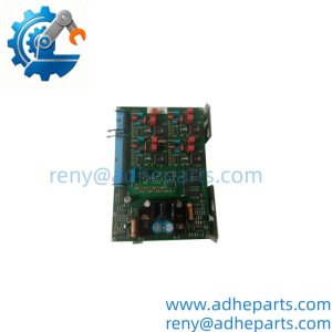
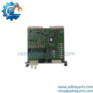
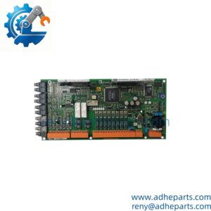
The GE DS200TCCAG1BAA is a board for the Speedtronic Mark V turbine control platform. It sits in the Mark V rack and carries control or interface signals for the turbine system. The exact function depends on the build — I cannot tell from the model number alone whether this is a turbine control card, a terminal board, or an interface module. I am not going to guess.
Here is what I can tell you as a straight answer: on Mark V hardware, compatibility is revision-specific. A board with the right part number and the wrong revision letter will initialize and still fail under load. Before you order, read the revision letter off your existing board and compare it to the replacement. If you send me a photo of the board label and the cabinet it came out of, I will confirm what you are looking at against the OEM documentation.
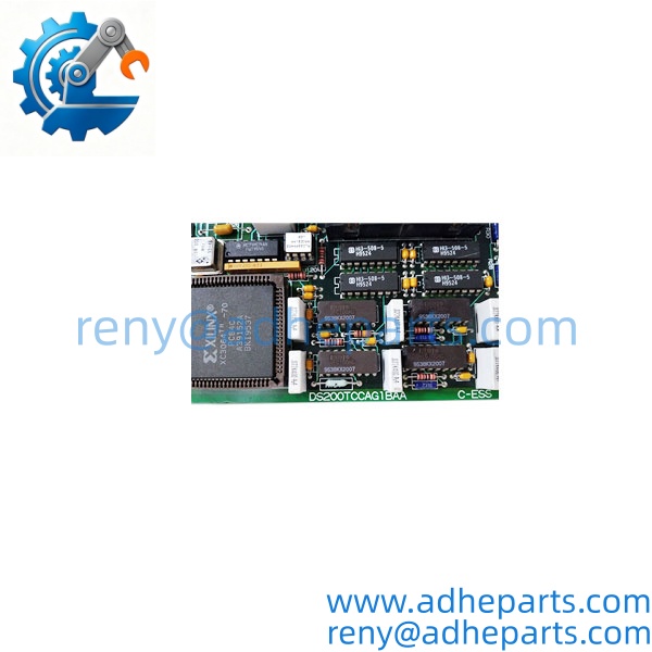
DS200TCCAG1BAA
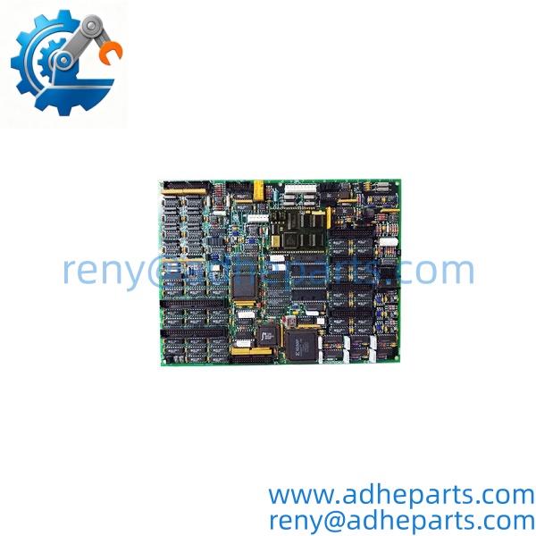
DS200TCCAG1BAA
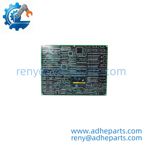
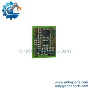
DS200TCCAG1BAA
Application Scenarios & Field Experience
Part 1 – Narrative Paragraph
The failure that costs the most downtime on a Mark V turbine is a board that passes a power-up test and still drops signals under load. I have seen a crew replace a control board twice and still have the fault because the real problem was a marginal connector or a field wiring short. On this platform, the board is rarely the only thing that can fail. Before you order a replacement, check the on-board fuses, the connector seating, and the field wiring. Then check the revision letter against your system’s firmware. A board with the right part number and the wrong revision will initialize and still cause a trip.
Part 2 – Numbered List (Application Scenarios)
- Gas Turbine Control – Turbine Control Interface – The board carries control signals between the Mark V controller and the turbine systems. A dropout here shows up as a control fault and a unit trip.
- Steam Turbine Control – Auxiliary System Interface – The board interfaces with auxiliary systems on the Mark V platform. A failed board drops those signals from the controller’s view.
- Combined Cycle Plants – Mark V Retrofit Support – Used where a Mark V system is still in service and the OEM no longer stocks the exact revision. Replacement is often the only path short of a full control system migration.
- Industrial Turbines – Control System Maintenance – The board is a spare for plants running Mark V controls on industrial turbines. The on-board diagnostics help isolate the fault to the board or the field wiring.
Part 3 – Short Field Story
A combined cycle plant had a gas turbine that tripped on a control fault during a load change. The crew replaced the DS200TCCAG1BAA board and the fault came back two days later. We asked them to check the on-board fuses and the field wiring. The fuses were blown, and the field cable had a chafed conductor that was shorting intermittently against the conduit. The plant replaced the cable and installed the correct revision board. The fault cleared. The board had been doing its job — the field wiring was the problem.
Standard Operating Procedure (SOP) for Quality Control
- Visual & Origin Inspection – We verify the GE marking, the DS200TCCAG1BAA model string, and the date code. We inspect the backplane connector for bent pins and the board for evidence of heat damage, rework, or moisture. A board with a cracked connector or burned traces is rejected.
- Revision Documentation – We read and photograph the full model string, the revision letter, all jumper and switch settings, and the on-board fuse ratings. That record ships with the board so you can compare it against the unit you are replacing.
- Fuse Verification – We check every on-board fuse for continuity and confirm the rating matches the OEM specification. A board with a blown or wrong-rated fuse is corrected before shipping.
- Power-Up Self-Test – The board is inserted into a known-good Mark V test rack. We verify it initializes without a backplane fault and that the controller recognizes the board type.
- Signal Path Verification – We verify the board’s signal path against a test fixture and confirm the outputs match the commanded values.
- Connector Integrity Test – We mate and unmate the backplane connector ten times to confirm the contacts do not deform and the retention mechanism holds. A loose board causes intermittent faults that are hard to diagnose in the field.
- ESD-Safe Packaging – The board is wrapped in anti-static film, seated in a conductive foam insert with the connectors protected by rigid shrouds, and packed in a double-wall carton with static warning labels.
Frequently Asked Questions (FAQ)
Q1: What is the function of the DS200TCCAG1BAA?
A: I cannot confirm the exact function from the model number alone. It is a Mark V board from the turbine control group, but it could be a turbine control card, a terminal board, or an interface module. Send us a photo of the label and the cabinet it came out of, and we will confirm it against the OEM documentation before you order.
Q2: Will this board work in my Mark V rack without a firmware change?
A: Only if the revision letter matches or is compatible with your system’s firmware. The revision letter on this board governs the firmware image, and a mismatched revision can initialize and still drop signals under load. Read the revision letter off your existing board and compare it to the replacement before you order.
Q3: What is the warranty on this board?
A: We offer a 12-month warranty from the ship date. It covers component failure, backplane connector failure, and signal path failure under normal operating conditions. It does not cover damage from hot-swapping the board with the rack energized, bent pins from forced insertion, or field wiring faults that cause fuse failure. We test every board in a live Mark V rack before it ships.
Q4: Do you have this exact board in stock?
A: Mark V inventory moves quickly, and stock varies by revision. Confirm availability before you plan an outage. If we are out of the revision you need, we will tell you what we actually have rather than quote a date we cannot hold.
Q5: Any installation pitfalls I should watch for?
A: Four. First, power down the Mark V rack before inserting or removing the board — these boards are not hot-swap capable. Second, record the revision letter, all jumper and switch settings, and the fuse ratings from the old board before you remove it. Third, check the field wiring for shorts or chafing before you install the replacement; a field fault will damage the new board. Fourth, after the swap, verify the board communicates with the controller and the signal path is correct before you return the unit to service. A board that powers up is not necessarily communicating correctly.