Description
Note: Many products are not yet listed. Please contact us for more product information. Our supply channels are constantly expanding, and we currently have 20 stable shared supply channels. Please confirm the model, product, price, and all other necessary information with customer service before placing an order. We offer new, refurbished, and used products, and prices are adjusted according to the year of the item you require.
Product Introduction
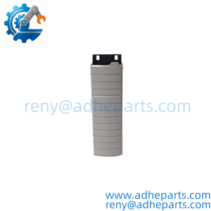
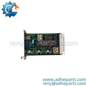
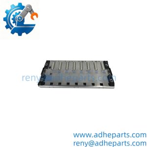
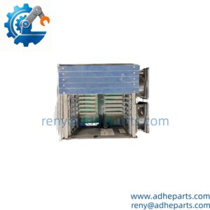
When large power‑plant DCS racks suffer scattered remote I/O timeouts, many technicians overlook the base hardware sitting beneath the controller electronics. This rack‑mount base forms the physical backbone for Ovation remote node modules, distributing backplane power and carrying high‑speed local I/O bus traffic across cabinet marshalling hardware. The rotary dial near the third terminal block from the left sets hardware node ID; mismatched dial positions create duplicate‑node bus conflicts, —though your mileage may vary depending on how the controller project was originally configured. No processing logic lives inside this passive‑active base; all decision‑making runs on the plugged‑in remote node modules.
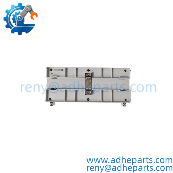
1C31205G01
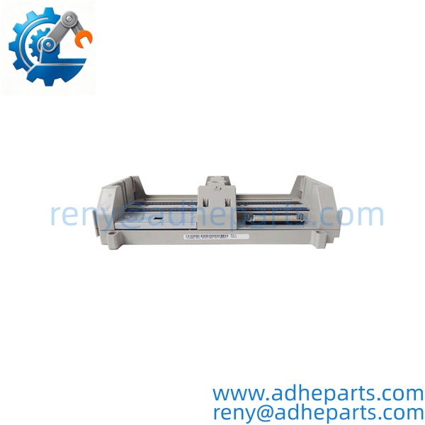
1C31205G01
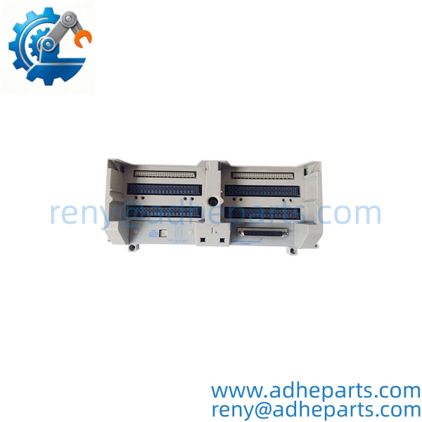
1C31205G01
Key Technical Specifications
| Parameter | Value |
|---|---|
| OEM Part Number | 1C31205G01 |
| Host Platform | Emerson Ovation Distributed Control System |
| Module Slot Capacity | Max 2 remote node plug‑in modules |
| Native I/O Branches | 2 direct local I/O branch interfaces |
| Expansion Port | D‑sub connector supporting up to 6 additional I/O branches |
| Address Setting | Mechanical rotary selector switch (hardware node ID) |
| Auxiliary Power | 24 VDC supplied via rack backplane |
| Status Indicators | Power, bus activity, fault LED indicators |
| Operating Ambient Temperature | 0 °C … +55 °C |
| Humidity Range | 5%‑95% RH non‑condensing |
| Mounting | Standard Ovation cabinet rack‑mount form factor |
| Compatibility Note | Matches Ovation remote node controller module series only |
Field Application & Technical Pitfalls (The Engineer’s Guide)
Critical industrial scenarios:
- Fossil‑fuel power‑plant boiler and turbine auxiliary I/O cabinets spread across large control‑room footprints.
- Water‑treatment facility DCS installations where I/O marshalling sits separate from main controller racks.
- Combined‑cycle plant remote I/O enclosures handling burner management and interlock signal collection.
Technical pitfalls to avoid
- Rotary address switch mis‑setting: Changing the dial position while the base stays powered can trigger duplicate node addresses on the local I/O bus. Well, technically communication may not fail instantly, but intermittent bus collisions appear under heavy process load. Always power down before adjusting hardware node ID.
- Damaged D‑sub expansion connector pins: The D‑sub port for extended I/O branches uses fine pins; rough cable insertion bends contacts. Bent pins produce partial‑branch drop‑outs that do not trigger clear hardware fault alarms.
- Mismatched remote node module generations: Older‑revision remote node electronics will physically seat on this base, yet signal timing shifts and bus retries multiply. Verify exact remote‑node module part numbers before pairing hardware.
Hypothetical field anecdote: A power‑plant team swapped out a faulty remote node module during a weekend outage and reused the existing 1C31205G01 base. One technician nudged the rotary address dial while re‑routing adjacent cabling, but no one checked the node ID afterward. On Monday startup, half the rack’s analog inputs vanished at random intervals. Engineers spent four hours chasing controller software settings before spotting the misaligned rotary switch position. No hardware sustained damage, yet critical boiler monitoring points became unreliable during startup sequence.
Quality Control (QC) SOP & Transparency
- Inbound Verification: Cross‑check physical part marking against OEM 1C31205G01 reference; inspect all backplane slot contacts, D‑sub expansion connector pins and rotary address dial for wear or bending; examine housing for cracks or rack‑mount scratch marks; review OEM packaging for new‑surplus stock.
- Live Rig Testing: Mount unit in Ovation test cabinet; apply 24 VDC backplane supply; verify LED power‑on sequence; install reference remote node module, toggle rotary address dial through multiple positions, confirm bus handshake and node identification complete without fault flags.
- Parameter Testing: Perform continuity checks across direct I/O branch paths and D‑sub expansion contacts; rule out internal resistive shorts or open traces on the base backplane circuit.
- Final QA & Packaging: Complete second visual inspection of connectors and mechanical dial function; place unit inside static‑shield anti‑static bag; apply QC‑passed sticker printed with test date; add rigid foam padding to shield connector pins during transit.
Frequently Asked Questions (FAQ)
Q: Can I hot‑swap remote node modules while the 1C31205G01 base remains energized? A: Ovation permits hot‑swap of upper remote node electronics. Do not touch rotary address dial or D‑sub expansion cables while powered. Full lock‑out‑tag‑out is required for base assembly removal.
Q: Will 1C31205G01 work with every generation of Ovation remote node controller modules? A: It physically accepts most modules. Firmware and hardware revision matching still matters. Mismatched revisions raise bus retry rates. Verify exact load capacity with the OEM datasheet.
Q: What warranty terms apply for this base assembly? A: Standard 12‑month warranty covers test‑verified hardware defects. Warranty does not cover bent connector pins, cracked housing, or damage caused by incorrect address‑switch adjustments under power.
Q: After replacing the whole 1C31205G01 base, do I need to reload controller application logic? A: No. Control logic resides in the main Ovation controller, not inside this base. Confirm hardware node ID via rotary dial, then validate all I/O branch points from the operator station.
Q: How can I tell genuine OEM 1C31205G01 apart from rebuilt units? A: Authentic units carry molded or laser‑etched part numbers on the plastic housing. Rebuilt assemblies often show scratch wear on rack‑mount edges or minor hand‑rework solder marks on backplane traces. Avoid units relying purely on adhesive sticker labels.
Q: Some of my I/O branches go offline intermittently. What should I inspect before replacing the base? A: First power‑cycle the remote node module. Next inspect D‑sub expansion connector for bent or dirty pins, and confirm rotary address dial has not drifted from documented node number. Many intermittent issues trace to mechanical contacts rather than base‑circuit failure.